
I don’t know what AFAM stands for – it’s an Italian abbreviation – but the device is basically a small computer that controls the vehicle’s differential locks and transfer gearbox Power Take Off (PTO), if fitted. The problem I have, is that the software doesn’t function how I would like, which can be very frustrating when driving off road. I have therefore decided to replace the AFAM with an Arduino Due computer (Arduino) and use my own software to achieve the performance I want.
The main issues I have with the AFAM are:
- When a lock is selected, if it doesn’t engage quickly, the AFAM will sometimes (but not always) de-select the lock whilst I’m trying to manoeuvre to get the lock to engage. This is the biggest issue I have with the AFAM.
- When a lock is selected but doesn’t engage, it can’t be de-selected without turning off the ignition.
- If the intention is to engage all the locks, the AFAM will only allow selection of one lock at a time. Only after one lock is engaged can the next one be selected. They also have to be engaged in sequence: centre, rear, front.
The Interface to the truck
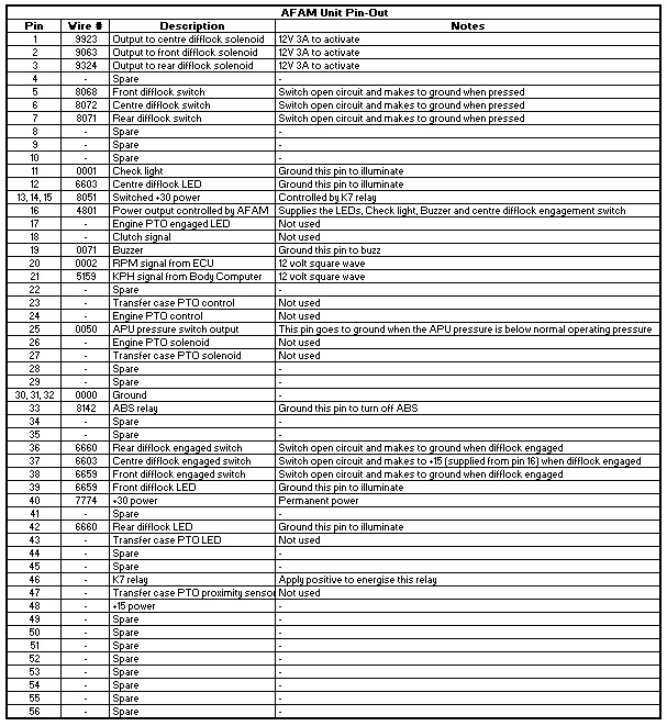
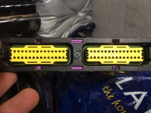
The AFAM has a 56-pin connector and these are the pins that are used:
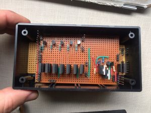
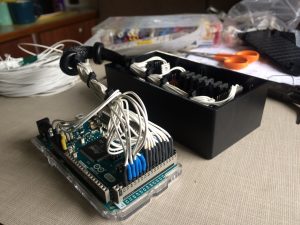
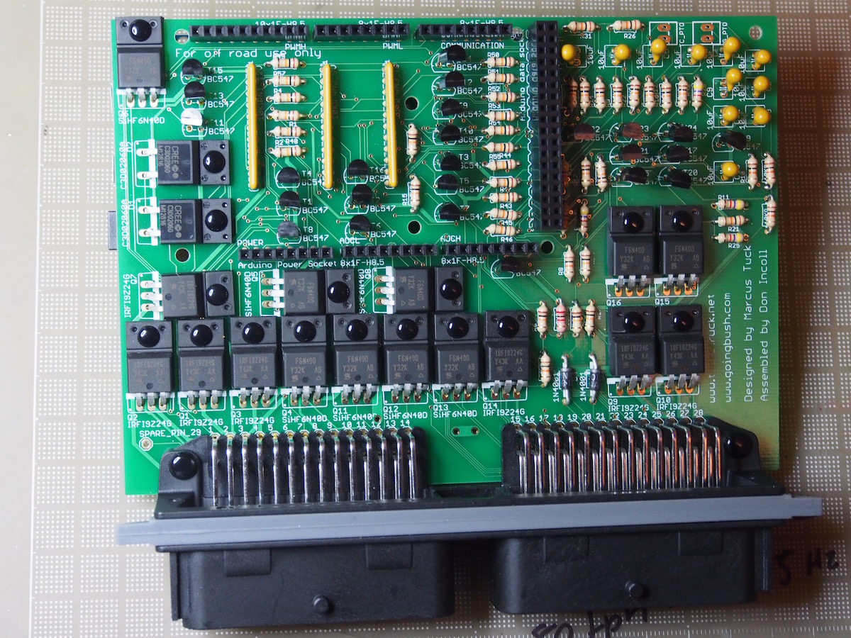
 Obviously, the voltage and power levels required by the truck far exceed the capabilities of the Arduino computer on its own. Therefore, an electronic interface was required. Here is my prototype design (there have been a number of changes for the production version):
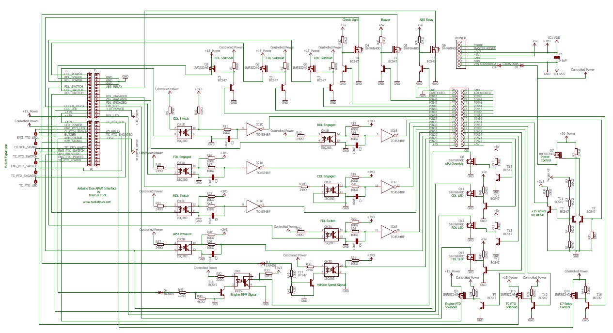 Click on this link to see a pdf of the circuit diagram that can be enlarged with better quality than the diagram above AFAM Interface Circuit Diagram
Circuit Description
Outputs
I have used 2 basic circuit types on the outputs of the Arduino Due to switch power:
(i) For outputs that require a positive power feed, a BC547 NPN transistor is used to switch a P Channel FET (IRFI9Z24G). These FETs are rated at 8.5 amps, so can easily handle the 3 amp requirement for the differential lock solenoid valves.
When the output pin on the Arduino is switched HIGH, the BC547 is switched on. With the BC547 on, the voltage on the Gate of the FET is taken low and energises the FET. With the FET on, power is supplied to the load through the FET’s Drain.
When the output pin on the Arduino is switched LOW, the BC547 is switched off. With the BC547 off, the voltage on the Gate of the FET is taken high by the 10K resistor and switches off the FET. With the FET off, power is no longer supplied to the load through the FET’s Drain.
(ii) For outputs requiring an earth, a BC547 NPN transistor is used to switch an N Channel FET (SiHF6N40D). These FETs are rated at 6 amps, so can easily handle the small load requirements for the various lights, relays and buzzer.
When the output pin on the Arduino is switched HIGH, the BC547 is switched on. With the BC547 on, the voltage on the Gate of the FET is taken low and energises the FET. With the FET on, an earth is supplied to the load through the FET’s Drain.
When the output pin on the Arduino is switched LOW, the BC547 is switched off. With the BC547 off, the voltage on the Gate of the FET is taken high by the 10K resistor and switches off the FET. With the FET off, the earth is no longer supplied to the load through the FET’s Drain.
Switch Inputs
The Arduino Due only uses 3.3 Volts for its control, so there needs to be some protection from the vehicle’s normal voltages. I have achieved this using opto-isolators on most of the inputs. A suitable value resistor was chosen for the opto-isolators LED, based on its current requirements and vehicle voltage.
As electrical switches can be quite ‘noisy’ for computers, I have also ‘de-bounced’ the switch signals using a simple capacitor/resistor network. When the output of the opto-isolator is off, the capacitor is charged through the two 10k Ohm resistors, taking 200 mS. However, when the opto-isolator is turned on, the capacitor is discharged through one 10 k ohm resistor, taking 100 mS. I could have installed a diode over the resistor, connected directly to the capacitor, so that the charge and discharge times were the same, but it is not that critical for this application. These delays will stop any momentary pulses (generated by the switch as it is activated or deactivated) from being mistaken by the computer as multiple switch operations – and hence it is de-bounced!
To further enhance this performance, I then pass the signal through a Schmitt trigger. As the Schmitt trigger is triggered at set voltages, the output from the capacitor is ‘squared’ up and makes life easier for the computer. Also, due to these trigger voltages, the actual delay produced by the capacitor becomes 120 mS when switching from low to high, and 54 mS switching high to low (the time it takes the capacitor to change charge to the trigger voltage).
The Centre Differential Lock (CDL) has a slight variation on the design as it switches HIGH rather than to earth when it engages. You can see in the diagram above that the opto-isolator’s LED is connected to earth and the ‘CDL engaged’ signal is fed through the 249R resistor to energise the LED.
Speed and RPM Inputs
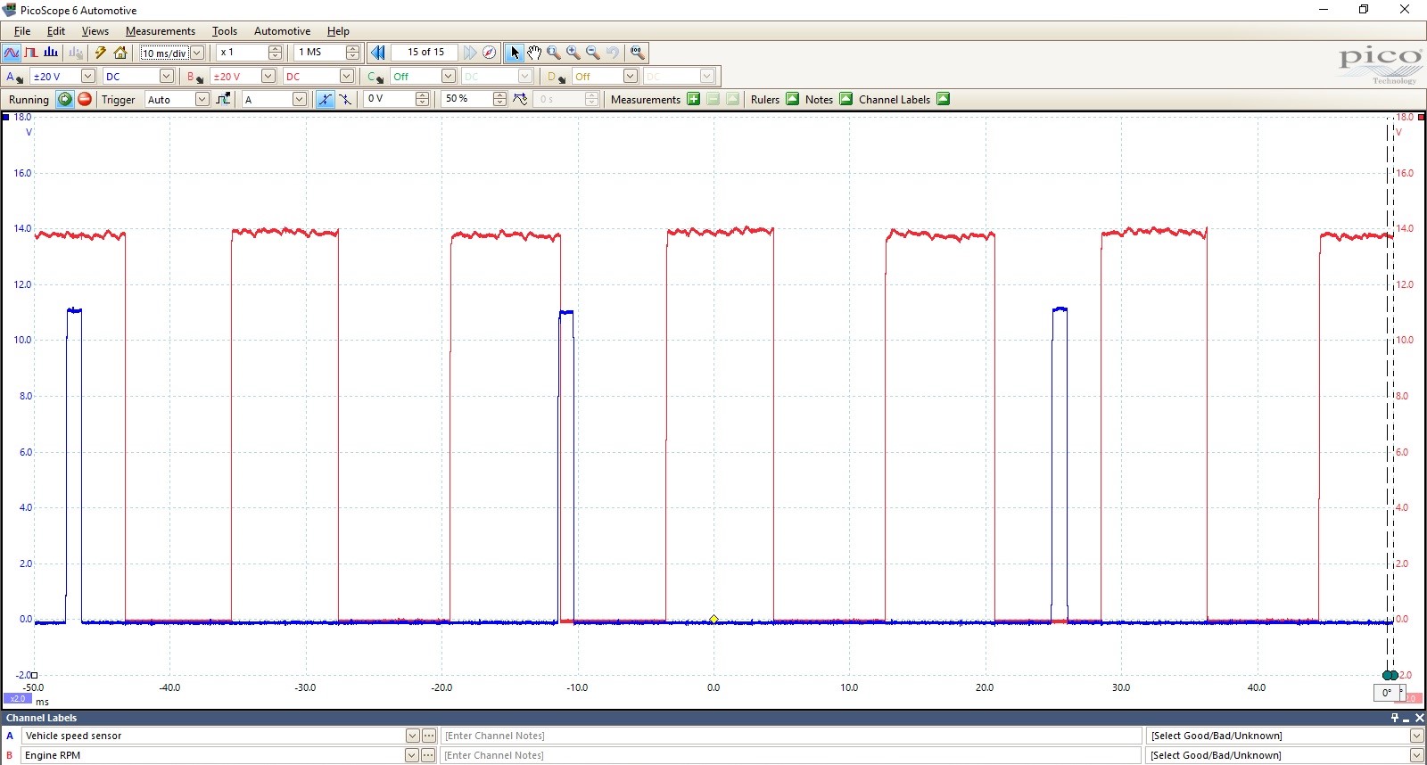
The vehicle speed and rpm signals are 13 volt square waves, but require the interface to have a higher resistance than would be achieved by simply connecting them to the opto-isolators. I therefore passed the signal through a diode (to provide some protection to the signals’ source) and then used a simple voltage divider (to provide the higher resistance and also to lower the signal voltage so that it could drive a BC547 transistor). The transistor then switches the opto-isolator and its output goes to the Arduino input.
 Power Control
To prevent the computer from shutting down when the ignition is turned off for short periods (e.g. if you stall and have to restart the engine) I have added a power control circuit. When the ignition is turned on, the +15 supply goes high, which switches on transistor T7 and T 11 through a potential divider circuit (you could cut down on the number of resistors, I just used what I had available). With T7 on, Q7 is also turned on and power is supplied to the circuit from the +30 supply. T11 is used to provide an input to the Arduino, so it can detect when there is a +15 supply. The Arduino is programmed to switch on T8, which in turn can hold Q7 on, providing a supply to the circuit even if the +15 supply goes off. The Arduino can then turn off T8 when it wants to shut down, a set time after the +15 supply is off. I found that T8 remained on, even when the Arduino port went low; this meant that the circuit never shut down! I remedied the problem by installing a pull-down resistor between the base of T8 and ground.
Arduino Power Supply
The Arduino has a maximum voltage input range of 6 to 16 V, however the recommended range is 7 to 12 V. I have therefore installed two C3D02060A Diodes in-series, in the supply line to the Arduino. These diodes were chosen as they have quite a large voltage drop across them (1.5V each) and so keep the supply voltage to the Arduino below 12V. The C3D02060A Diodes are rated at 8 amps (65 amp surge!) and will be subjected to less than 1 amp, so no heat sink has been used.
Miscellaneous Circuits
The K7 relay is used to provide power for the differential lock and PTO solenoids. It is effectively a safety feature that prevents all the solenoids from operating unless it is active. I have also installed FETs for the PTOs that I don’t have, simply because the vehicle has the wiring and I may find a use for these circuits in the future. I have also installed a FET labelled as ‘APU override’. There have been several cases where the APU pressure switch fails and you can no longer engage a lock. Sometime in the future I am looking to install a pressure sensor in the APU and will be able to control the APU using the ‘APU override’ circuit (should my APU pressure switch fail). In theory, I should have been able to drive the N channel FETs directly from the Arduino output ports. The FET specification states that 3 volts is sufficient, however, I found that the 3.3 volts from the Arduino was not enough and so added the BC547s to provide 5 volts switching for the FETs.
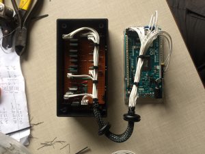
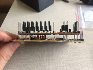
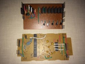
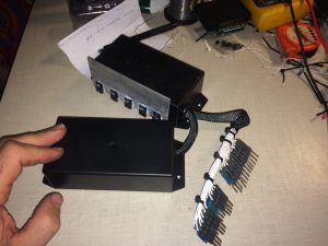
Board Construction
I constructed the circuit on two boards, a switch logic board and a transistor board. I then mounted the boards above one another to save space. The FETs I have used are rated at over 6 amps each and as most loads will be less than 100 mA I have not bothered with heat sinks. The exception to this are the 5 FETs that are being used for the Diff locks and PTO solenoids where their load could be up to 3 amps (the fuse size). I have mounted these externally on a heat sink. A nice feature of the SiHF6N40D and IRFI9Z24G is that their ‘tab’ is insulated and so no electrical isolation is required.
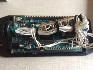

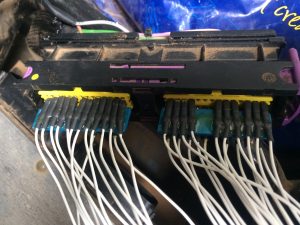
AFAM Plug
I was unable to get the correct connector for the AFAM plug, so made up the individual wires, inserted them into the plug and then glued the pins to strips of plastic between the pins. This holds the pins in place and allows them to be plugged in and out. This is fine for testing, but once I am happy with the circuit I will replace this arrangement with a proper plug and socket.
The Software
There are various parameters that can easily be changed within the software. I have listed them at the start of the program it’s not necessary to hunt through the code to change them. I don’t know what the Iveco timings are for the APU and Power, but for the locks’ engagement and disengagement speeds I have used the original values:-
- CDLmaxSpeed = 80; speed (kph) at which the CDL will disengage
- CDLmaxEngage = 40; maximum speed (kph) at which the CDL can be engaged
- RDLmaxSpeed = 40; speed (kph) at which the RDL will disengage
- RDLmaxEngage = 20; maximum speed (kph) at which the RDL can be engaged
- FDLmaxSpeed = 30; speed (kph) at which the FDL will disengage
- FDLmaxEngage = 15; maximum speed (kph) at which the FDL can be engaged
- Tyre = 356; The number of tyre revolutions per km, (356 is for a Michelin 255/100 R 16 XZL tyres)
- APUmaxON = 3000; maximum time the APU pump should be running for in milliseconds before a warning is generated
- PWRon = 5000; time for power to remain on after +15 is off in milliseconds
Vehicle speed calculation
For the software to accurately calculate the vehicle’s speed, it is necessary to enter the number of times the tyres rotate in one kilometre. The value is stored in “int const Tyre = 356;”. 356 is the correct value for Michelin 255/100 R16 XZL tyres. This value is probably close enough for most other tyres commonly fitted to the Daily 4×4.
Software Operation
I have tried to copy the original AFAM’s operations as much as possible. The few changes I have made are:
a) The locks must still be selected in order, Centre, Rear, Front, but it will now accept the button press even if the previous lock has not engaged. It will not attempt to engage the second lock until the first is engaged, but it will automatically attempt to engage the second one once the first lock is engaged. For example, if Centre, Rear and then Front are selected in quick succession, it will try to engage the Centre lock first. As soon as the Centre lock is engaged, it will attempt to engage the Rear lock; and when the Rear lock is engaged it will attempt the Front lock.
b) The locks don’t need to be deselected manually in order. For example, if all the locks are engaged, deselecting the Centre lock will first deselect the Front lock. Once the front has disengaged, the Rear will be deselected and when that is disengaged, the Front will finally be deselected. They can still be deselected individually as well.
c) When a lock is selected, the computer will not time-out and it will continue to try and engage the lock until it is told to stop!
d) A lock can be deselected even if it has not completely engaged.
e) There is now a stall warning feature! On rough and noisy roads, it is possible to be distracted when using the high gears and slow down to the point that the engine can stall. Slowing down to the point that the engine speed reduces to 700 rpm, will make the ‘check’ light and buzzer come on. If the clutch is dipped at this point, the engine will pick up again and a lower gear can be selected.
Update 23 May 17
Improvements to the software
I have cleaned up the code and made extensive use of functions (thanks for the advice on this, Oliver!). This has made the code run much faster. I have now spent several hours driving through the jungle of Suriname and am pleased to report much better functionality than I had with the original AFAM.
Following a request from a fellow Daily 4×4 user, Don (www.goingbush.com) I have also added a function which allows only the RDL to be selected. This would be used, for example, to move the vehicle sideways when trying to negotiate some types of obstacle. This mode is entered when stationary by pressing the RDL and FDL switches together. It will disengage at the FDL dis-engagement speed and can be de-selected by pressing the RDL switch. The CDL can also be engaged when the RDL is locked, in which case the system reverts to normal operation.
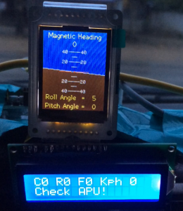
Note on future development
This will be the last update to this version of software (i.e. for the AFAM only). I am now progressing a more advanced version which includes an artificial horizon to monitor the roll and pitch angles while driving off road. I have added the 9 axis motion shield to the AFAM Due and a serial connection to another computer controlling a display on the dash board. This new ‘project’ will be added to the website and a link posted here when it is more complete. Here is a picture of the Artificial Horizon TFT screen and LCD display of the prototype to ‘wet your appetite’ 😉
Update 2 March 18
The production printed circuit boards are a great improvement over my intial prototype. They are a drop in replacement for the original AFAM PCB. There are more than 30 in use in Europe, Africa, Australia and the Americas so far!
Below is version 1.7 of the AFAM software, the production version are now running version 11.7!
/********************************************************************************
  This program is for running an Arduino Due in place of the Iveco AFAM computer
  in an Iveco, Daily 4x4 55S17W.  This software only operates the differential
  locks and indicators and does not have any PTO functionality. The software was
  written and developed by Marcus Tuck for personal use, for more details see
  www.tuckstruck.net/truck-and-kit/modifications-and-repairs/afam-computer-replacement/

  This program was made available in the hope that it will be useful to others,
  but without any warranty; without even the implied warranty of merchantability
  or fitness for purpose.

  Software Version 1.7

***********************************************************************************************
  AFAM Abbreviations
  CDL = Centre Differential Lock
  RDL = Rear Differential Lock
  FDL = Front Differential Lock
  APU = Auxiliary Power Unit, the hydraulic pump for the differential locks
  +15 = Vehicle power controlled by the ignition key
  +30 = Permanent vehicle power

  Note that the CDLL, RDLL, FDLL, CL, ABS, APUor and Buzz outputs are inverting so a HIGH is off and
  a LOW is on!
***********************************************************************************************/

//Variables that can be customised
int const CDLmaxSpeed = 80;       //speed (kph) at which the CDL will disengage,         (Iveco setting 80 kph)
int const CDLmaxEngage = 40;      //maximum speed (kph) at which the CDL can be engaged, (Iveco setting 40 kph)
int const RDLmaxSpeed = 40;       //speed (kph) at which the RDL will disengage,         (Iveco setting 40 kph)
int const RDLmaxEngage = 20;      //maximum speed (kph) at which the RDL can be engaged, (Iveco setting 20 kph)
int const FDLmaxSpeed = 30;       //speed (kph) at which the FDL will disengage,         (Iveco setting 30 kph)
int const FDLmaxEngage = 15;      //maximum speed (kph) at which the FDL can be engaged, (Iveco setting 15 kph)
int const APUmaxON = 4000;        //maximum time the APU pump should be running for in milliseconds before a warning is generated
int const PWRon = 5000;           //time for power to remain on after +15 is off in milliseconds

//System variables
int const LockUpdate = 500;       //sets the rate at which the status of the diff locks is checked (in ms)
int const KphUpdate = 500;        //sets the rate at which the vehicle speed is updated (in ms)
int const RpmUpdate = 500;        //sets the rate at which the RPM is updated (in ms)
int const FlashDuration = 250;    //interval for the 'Flash' of lights or buzzer in milliseconds
int const DurationBuzz = 300;     //used for the timing of the buzzer
int const DurationBuzzL = 1000;   //used for the timing of the buzzer, long
int const RPMconstant = 8000000; //used in the calculation of the engine RPM
int const KPHconstant = 225471;   //used in the calculation of the vehicle speed
int const TimeOutKPH = 230000;    //used in the calculation of the vehicle speed
int const TimeOutRPM = 45000;     //used in the calculation of the engine RPM
int vehicleSpeed = 0;             //used to store the vehicle speed (kph)
int APUpressure = HIGH;           //used to store the status of the APU pressure switch
int EngineRPM = 0;                //used to store the engine RPM
int kph1 = 0;                     //used to average out the kph calculations
int kph2 = 0;                     //used to average out the kph calculations
int kph3 = 0;                     //used to average out the kph calculations
int kph4 = 0;                     //used to average out the kph calculations
int rpm1 = 0;                     //used to average out the rpm calculations
int rpm2 = 0;                     //used to average out the rpm calculations
int rpm3 = 0;                     //used to average out the rpm calculations
int rpm4 = 0;                     //used to average out the rpm calculations
int BuzzCDL = LOW;                //used for the buzzer function when the CDL engages or disengages
int BuzzRDL = LOW;                //used for the buzzer function when the RDL engages or disengages
int BuzzFDL = LOW;                //used for the buzzer function when the FDL engages or disengages
int BuzzCDLsw = LOW;              //used for the buzzer function when the CDL switch is pressed
int BuzzRDLsw = LOW;              //used for the buzzer function when the RDL switch is pressed
int BuzzFDLsw = LOW;              //used for the buzzer function when the FDL switch is pressed
int Flash = LOW;                  //used for the timing of the flashing LEDs and buzzer
int CDLengaged = LOW;             //used to store the status of the CDL
int RDLengaged = LOW;             //used to store the status of the RDL
int FDLengaged = LOW;             //used to store the status of the FDL
int BuzzFlag = 0;                 //used for the timing of the buzzer
int BuzzFlagS = 0;                //used for the timing of the buzzer
int BuzzFlagL = 0;                //used for the timing of the buzzer
int CDLLflag = 0;                 //used for the diff lock light control
int RDLLflag = 0;                 //used for the diff lock light control
int FDLLflag = 0;                 //used for the diff lock light control
int RDLonly = LOW;                //used for locking only the RDL
int CycleCount = 0;               //for counting how many times the code runs per second
int CycleCountTotal = 0;          //for counting how many times the code runs per second
long CycleMillis = 0;             //for counting how many times the code runs per second
long Ptime = 0;                   //used in the calculation of the vehicle speed and engine RPM
long previousMillisFlash = 0;     //used for the timing of the flashing LEDs
long previousMillisBuzz = 0;      //used for the timing of the buzzer
long previousMillisBuzzL = 0;     //used for the timing of the buzzer
long previousMillisAPU = 0;       //used for the timing of the APU pump
long previousMillisPWR = 0;       //used for the timing of the power control
unsigned long lastLockUpdate = 0; //to store the last lock update time stamp
unsigned long lastKphUpdate = 0;  //to store the last speed update time stamp
unsigned long lastRpmUpdate = 0;  //to store the last rpm update time stamp
volatile int CDLswitch = HIGH;    //used to store the CDL switch position
volatile int RDLswitch = HIGH;    //used to store the RDL switch position
volatile int FDLswitch = HIGH;    //used to store the FDL switch position

//Arduino Due pin connections to the truck systems (if you have built yours differently, just change the pin allocations here)
int PWR    = 36; //Power control (+30)
int Power  = 34; //Power sense (+15)
int CDLSo  = 43; //CDL solenoid
int RDLSo  = 45; //RDL solenoid
int FDLSo  = 41; //FDL solenoid
int TCpto  = 32; //TC PTO solenoid
int EngPTO = 30; //Engine PTO solenoid
int CDLL   = 24; //CDL LED
int RDLL   = 26; //RDL LED
int FDLL   = 28; //FDL LED
int CL     = 47; //Check light
int Buzz   = 49; //Buzzer
int ABS    = 51; //ABS relay
int CDLSw  = 39; //CDL switch
int RDLSw  = 31; //RDL switch
int FDLSw  = 29; //FDL switch
int CDLE   = 33; //CDL engaged signal
int RDLE   = 37; //RDL engaged signal
int FDLE   = 35; //FDL engaged signal
int KPH    = 25; //Vehicle speed signal
int APU    = 27; //APU pressure switch
int RPM    = 23; //RPM speed signal
int APUor  = 22; //APU pressure switch override control
int K7     = 38; //K7 relay control (this relay controls power to all the diff lock and PTO solenoids)

void setup() {
  //This section sets up the Arduino Due's pin operating modes
  pinMode(PWR, OUTPUT);   //Power control (+30)
  pinMode(CDLSo, OUTPUT); //CDL solenoid
  pinMode(RDLSo, OUTPUT); //RDL solenoid
  pinMode(FDLSo, OUTPUT); //FDL solenoid
  pinMode(TCpto, OUTPUT); //TC PTO solenoid
  pinMode(EngPTO, OUTPUT);//Engine PTO solenoid
  pinMode(CDLL, OUTPUT);  //CDL LED
  pinMode(RDLL, OUTPUT);  //RDL LED
  pinMode(FDLL, OUTPUT);  //FDL LED
  pinMode(CL, OUTPUT);    //Check light
  pinMode(Buzz, OUTPUT);  //Buzzer
  pinMode(ABS, OUTPUT);   //ABS relay
  pinMode(APUor, OUTPUT); //APU pressure switch override control
  pinMode(K7, OUTPUT);    //K7 relay control (this relay controls power to all the diff lock and PTO solenoids)
  pinMode(Power, INPUT);  //Power sense (+15)
  pinMode(CDLSw, INPUT);  //CDL switch
  pinMode(RDLSw, INPUT);  //RDL switch
  pinMode(FDLSw, INPUT);  //FDL switch
  pinMode(CDLE, INPUT);   //CDL engaged signal
  pinMode(RDLE, INPUT);   //RDL engaged signal
  pinMode(FDLE, INPUT);   //FDL engaged signal
  pinMode(KPH, INPUT);    //Vehicle speed signal
  pinMode(APU, INPUT);    //APU pressure switch
  pinMode(RPM, INPUT);    //RPM speed signal

  digitalWrite(PWR, HIGH); //locks on the power to +30 in case the +15 supply goes off

  //This section makes sure the Diff lock solenoids, K7 relay and APU override are off
  digitalWrite(CDLSo, LOW); digitalWrite(RDLSo, LOW); digitalWrite(FDLSo, LOW); digitalWrite(K7, LOW); digitalWrite(APUor, HIGH);

  //This section switches off the lights and buzzer after half a second, lights test.
  delay(500); digitalWrite(Buzz, HIGH); digitalWrite(CDLL, HIGH); digitalWrite(RDLL, HIGH); digitalWrite(FDLL, HIGH); digitalWrite(CL, HIGH); digitalWrite(ABS, HIGH);

  //sets up the difflock switches as interrupts
  attachInterrupt(digitalPinToInterrupt(CDLSw), CDLswISR, RISING); //enables the CDL switch as an interrupt, active when switching from low to high and changes state of the CDLswitch variable
  attachInterrupt(digitalPinToInterrupt(RDLSw), RDLswISR, RISING); //enables the RDL switch as an interrupt, active when switching from low to high and changes state of the RDLswitch variable
  attachInterrupt(digitalPinToInterrupt(FDLSw), FDLswISR, RISING); //enables the FDL switch as an interrupt, active when switching from low to high and changes state of the FDLswitch variable

  //this section ensures that the diff lock switches are set low after the interupts are initiated
  CDLswitch = LOW;
  RDLswitch = LOW;
  FDLswitch = LOW;

  Serial.begin(115200);                             //Initialize Serial Port (USB) to send information to a monitoring computer

  updateSpeeds();                                   //Updates the vehicle speed and rpm
  startPositions();                                 //Checks the start positions of the locks and re-engages them if required
}
/**********************************************************************************************************************************************************************************************
   Start of main program
 *********************************************************************************************************************************************************************************************/
void loop() {
  updateLocks();                  //sets the state of the diff lock variables
  buzzerControl();                //Controls the buzzer
  k7AbsFlash();                   //Controls the K7 relay, ABS and Flash function
  diffLockLightControl();         //Controls the diff lock lights
  diffEngagmentConditions();      //Controls the indications for the differential lock engagement conditions
  diffLockControl();              //Controls the diff locks
  checkLightControl();            //Controls the Check Light
  powerControl();                 //Controls the power to the Arduino Due
  rearDiffOnly();                 //Controls the rear diff only mode
  updateSpeeds();                 //Updates the vehicle speed and rpm
  sendTestData();                 //Sends test data to the laptop
}
/**********************************************************************************************************************************************************************************************
   End of main program
**********************************************************************************************************************************************************************************************/
void CDLswISR() {  //These are the functions performed when an interrupt is activated
  if (CDLswitch == HIGH) {
    CDLswitch = LOW; //changes state of the CDLswitch variable when the CDL switch is pressed
  } else {
    CDLswitch = HIGH;
  }
}
void RDLswISR() {
  if (RDLswitch == HIGH) {
    RDLswitch = LOW; //changes state of the RDLswitch variable when the RDL switch is pressed
  } else {
    RDLswitch = HIGH;
  }
}
void FDLswISR() {
  if (FDLswitch == HIGH) {
    FDLswitch = LOW; //changes state of the FDLswitch variable when the FDL switch is pressed
  } else {
    FDLswitch = HIGH;
  }
}

void updateLocks() {  //This function updates the diff lock variables; CDLengaged, RDLengaged and FDLengaged
  if ((millis() - lastLockUpdate) >= LockUpdate)
  {
    lastLockUpdate = millis();
    CDLengaged = digitalRead(CDLE); //sets the state of the CDLengaged variable
    RDLengaged = digitalRead(RDLE); //sets the state of the RDLengaged variable
    FDLengaged = digitalRead(FDLE); //sets the state of the FDLengaged variable
  }
}
void updateSpeeds() {  //This function updates the vehicleSpeed variables; kph, rpm
  if ((millis() - lastKphUpdate) >= KphUpdate)
  {
    lastKphUpdate = millis();
    kph1 = kph2; kph2 = kph3; kph3 = kph4;
    Ptime = pulseIn(KPH, HIGH, TimeOutKPH);          //measurement of the vehicle speed signal high duration in microseconds
    if (Ptime > 1) {
      kph4 = (KPHconstant / Ptime);                  //calculates the vehicle speed in kph from the duty cycle duration
      if (kph4 > (kph3 + (KphUpdate / 100))) {
        kph4 = kph3 + (KphUpdate / 100);             //captures any erroneously high calculations and caps them
      }
      if (kph4 < (kph3 - (KphUpdate / 100))) {
        kph4 = kph3 - (KphUpdate / 100);             //captures any erroneously low calculations and caps them
      }
      if (kph4 < 0) {                                //makes sure there is not a negative speed
        kph4 = 0;
      }
    }
    else {
      kph4 = 0;
    }
    vehicleSpeed = (kph1 + kph2 + kph3 + kph4) / 4;  //averages the output over 4 samples

  //This section updates the EngineRPM variable
  if ((millis() - lastRpmUpdate) >= RpmUpdate)
  {
    lastRpmUpdate = millis();
    rpm1 = rpm2; rpm2 = rpm3; rpm3 = rpm4;
    Ptime = pulseIn(RPM, HIGH, TimeOutRPM);           //measurement of the engine RPM signal high duration in microseconds
    if (Ptime > 1) {
      rpm4 = (RPMconstant / Ptime);                   //calculates the engine RPM from the low cycle duration
    if (rpm4 > (rpm3 + (RpmUpdate * 1.5))) {
        rpm4 = rpm3 + (RpmUpdate * 1.5);             //captures any erroneously high calculations and caps them
      }
      if (rpm4 < (rpm3 - RpmUpdate)) {
        rpm4 = rpm3 - RpmUpdate;                     //captures any erroneously low calculations and caps them
      }
      if (rpm4 < 0) {                                //makes sure there is not a negative speed
        rpm4 = 0;
      }
    } else {
      rpm4 = 0;
    }
    EngineRPM = (rpm1 + rpm2 + rpm3 + rpm4) / 4;      //averages the output over 4 samples
  }
}
}
void startPositions() {  //This function checks the starting position of the differential locks and if required reengages the solenoids if the speed is in limits and sets the flag for the diff lock to engaged
  if ((digitalRead(CDLE) == HIGH) && (vehicleSpeed <= CDLmaxEngage)) {
    digitalWrite(CDLSo, HIGH);
    CDLengaged = HIGH;
    CDLswitch = HIGH;
  }
  if ((digitalRead(RDLE) == HIGH) && (CDLengaged == HIGH) && (vehicleSpeed <= RDLmaxEngage)) {
    digitalWrite(RDLSo, HIGH);
    RDLengaged = HIGH;
    RDLswitch = HIGH;
  }
  if ((digitalRead(FDLE) == HIGH) && (RDLengaged == HIGH) && (CDLengaged == HIGH) && (vehicleSpeed <= FDLmaxEngage)) {
    digitalWrite(FDLSo, HIGH);
    FDLengaged = HIGH;
    FDLswitch = HIGH;
  }
}

void buzzerControl() {  //This function controls the buzzer
  if (BuzzFlag == 1) {
    if (millis() - previousMillisBuzz >= DurationBuzz) {
      digitalWrite(Buzz, HIGH);  //does a single buzz
      BuzzFlag = 0;
    } else {
      digitalWrite(Buzz, LOW);
    }
  }
  if (BuzzFlagL == 1) {
    if (millis() - previousMillisBuzzL >= DurationBuzzL) {
      digitalWrite(Buzz, HIGH);  //does a single long buzz
      BuzzFlagL = 0;
    } else {
      digitalWrite(Buzz, LOW);
    }
  }
  if (BuzzFlag == 2) {
    if (millis() - previousMillisBuzz >= DurationBuzz) {
      digitalWrite(Buzz, HIGH);  //does a single buz and then sends to the next line
      BuzzFlag = 3;
      previousMillisBuzz = millis();
    } else {
      digitalWrite(Buzz, LOW);
    }
  }
  if (BuzzFlag == 3) {
    if (millis() - previousMillisBuzz >= DurationBuzz) {
      previousMillisBuzz = millis();  //does a short gap and thends to first option for a single buzz thereby completing a 2 buzz sequence
      BuzzFlag = 1;
    }
  }
  if (BuzzFlag == 4) {
    if (Flash == LOW) {
      digitalWrite(Buzz, LOW);
    } else {
      digitalWrite(Buzz, HIGH);
    }
  }
  //This section does a single buzz for lock engagement and two buzzes for disengagement
  if (CDLengaged > BuzzCDL) {
    previousMillisBuzz = millis();
    BuzzFlag = 1;
    BuzzCDL = HIGH;
  }
  if (CDLengaged < BuzzCDL) {
    previousMillisBuzz = millis();
    BuzzFlag = 2;
    BuzzCDL = LOW;
  }
  if (RDLengaged > BuzzRDL) {
    previousMillisBuzz = millis();
    BuzzFlag = 1;
    BuzzRDL = HIGH;
  }
  if (RDLengaged < BuzzRDL) {
    previousMillisBuzz = millis();
    BuzzFlag = 2;
    BuzzRDL = LOW;
  }
  if (FDLengaged > BuzzFDL) {
    previousMillisBuzz = millis();
    BuzzFlag = 1;
    BuzzFDL = HIGH;
  }
  if (FDLengaged < BuzzFDL) {
    previousMillisBuzz = millis();
    BuzzFlag = 2;
    BuzzFDL = LOW;
  }
  //This section does a long buzz if a selection is made above its speed limit or out of sequence
  if ((CDLswitch == HIGH) && (CDLengaged == LOW) && (vehicleSpeed > CDLmaxEngage)) {
    previousMillisBuzzL = millis();
    BuzzFlagL = 1;
    CDLswitch = LOW;
  }
  if ((RDLswitch == HIGH) && (RDLengaged == LOW) && (vehicleSpeed > RDLmaxEngage)) {
    previousMillisBuzzL = millis();
    BuzzFlagL = 1;
    RDLswitch = LOW;
  }
  if ((FDLswitch == HIGH) && (FDLengaged == LOW) && (vehicleSpeed > FDLmaxEngage)) {
    previousMillisBuzzL = millis();
    BuzzFlagL = 1;
    FDLswitch = LOW;
  }
  if ((RDLswitch == HIGH) && (RDLengaged == LOW) && (CDLswitch == LOW)) {
    previousMillisBuzzL = millis();
    BuzzFlagL = 1;
    RDLswitch = LOW;
  }
  if ((FDLswitch == HIGH) && (FDLengaged == LOW) && (RDLswitch == LOW)) {
    previousMillisBuzzL = millis();
    BuzzFlagL = 1;
    FDLswitch = LOW;
  }
  if ((FDLswitch == HIGH) && (RDLonly == HIGH)) {
    previousMillisBuzzL = millis();
    BuzzFlagL = 1;
    FDLswitch = LOW;
  }
}
void k7AbsFlash() {  //This function toggles the Flash integer high and low at the rate defined in 'FlashDuration'.  It is used for the flashing lights or buzzer timings.
  if (millis() - previousMillisFlash >= FlashDuration) {
    previousMillisFlash = millis();
    if (Flash == LOW) {
      Flash = HIGH;
    } else {
      Flash = LOW;
    }
  }
  //This section controls the K7 relay and ABS
  if ((CDLswitch == HIGH) || (RDLonly == HIGH) || (CDLengaged == HIGH) || (RDLengaged == HIGH) || (FDLengaged == HIGH)) {
    digitalWrite(K7, HIGH);
    digitalWrite(ABS, LOW);
  } else {
    digitalWrite(K7, LOW);
    digitalWrite(ABS, HIGH);
  }
}
void diffLockLightControl() {  //This function controls the diff lock lights
  if (CDLLflag == 1) {
    digitalWrite(CDLL, LOW);
  }
  if (RDLLflag == 1) {
    digitalWrite(RDLL, LOW);
  }
  if (FDLLflag == 1) {
    digitalWrite(FDLL, LOW);
  }
  if (CDLLflag == 2) {
    digitalWrite(CDLL, Flash);
  }
  if (RDLLflag == 2) {
    digitalWrite(RDLL, Flash);
  }
  if (FDLLflag == 2) {
    digitalWrite(FDLL, Flash);
  }
  if (CDLLflag == 3) {
    digitalWrite(CDLL, HIGH);
  }
  if (RDLLflag == 3) {
    digitalWrite(RDLL, HIGH);
  }
  if (FDLLflag == 3) {
    digitalWrite(FDLL, HIGH);
  }
}
void diffEngagmentConditions() {  //This function controls the LED and Buzzer indications for the differential lock engagement conditions
  if ((CDLswitch == HIGH) && (CDLengaged == HIGH)) {
    CDLLflag = 1; //sets the CDL LED on if the CDL is selected and engaged
  }
  if ((RDLswitch == HIGH) && (RDLengaged == HIGH)) {
    RDLLflag = 1; //sets the RDL LED on if the RDL is selected and engaged
  }
  if ((FDLswitch == HIGH) && (FDLengaged == HIGH)) {
    FDLLflag = 1;  //sets the FDL LED on and makes the buzzer sound (at the Flash rate) if the FDL is selected and engaged
    BuzzFlag = 4;
  }
  if ((CDLswitch == HIGH) && (CDLengaged == LOW)) {
    CDLLflag = 2;; //sets the CDL LED to flash if the CDL is selected but not engaged
  }
  if ((RDLswitch == HIGH) && (RDLengaged == LOW)) {
    RDLLflag = 2; //sets the RDL LED to flash if the RDL is selected but not engaged
  }
  if ((FDLswitch == HIGH) && (FDLengaged == LOW)) {
    FDLLflag = 2; //sets the FDL LED to flash if the FDL is selected but not engaged
  }
  if ((CDLswitch == LOW) && (CDLengaged == HIGH)) {
    CDLLflag = 2; //sets the CDL LED to flash if the CDL is not selected but lock is engaged
  }
  if ((RDLswitch == LOW) && (RDLengaged == HIGH)) {
    RDLLflag = 2; //sets the RDL LED to flash if the RDL is not selected but lock is engaged
  }
  if ((FDLswitch == LOW) && (FDLengaged == HIGH)) {
    FDLLflag = 2;  //sets the FDL LED to flash and makes the buzzer sound (at the Flash rate) if the FDL is not selected but lock is engaged
    BuzzFlag = 4;
  }
  if ((CDLswitch == LOW) && (CDLengaged == LOW)) {
    CDLLflag = 3; //sets the CDL LED off if the CDL is not selected and is disengaged
  }
  if ((RDLswitch == LOW) && (RDLengaged == LOW)) {
    RDLLflag = 3; //sets the RDL LED off if the RDL is not selected and is disengaged
  }
  if ((FDLswitch == LOW) && (FDLengaged == LOW)) {
    FDLLflag = 3;  //sets the FDL LED off if the FDL is not selected and is disengaged
  }
}
void diffLockControl() {  //This function switches on and off the locks.  It checks the vehicle speed is in limits and that the other locks are selected and engaged or disengaged in sequence.
  if ((CDLswitch == HIGH) && (vehicleSpeed <= CDLmaxEngage)) {
    digitalWrite(CDLSo, HIGH);
  }
  if ((RDLswitch == HIGH) && (vehicleSpeed <= RDLmaxEngage) && (CDLengaged == HIGH)) {
    digitalWrite(RDLSo, HIGH);
  }
  if ((FDLswitch == HIGH) && (vehicleSpeed <= FDLmaxEngage) && (CDLengaged == HIGH) && (RDLengaged == HIGH)) {
    digitalWrite(FDLSo, HIGH);
  }
  if ((RDLonly == HIGH) && (vehicleSpeed <= FDLmaxEngage)) {
    digitalWrite(RDLSo, HIGH);
  }
  if ((CDLswitch == LOW) && (RDLengaged == LOW) && (FDLengaged == LOW)) {
    digitalWrite(CDLSo, LOW);
  }
  if ((RDLonly == LOW) && (((RDLswitch == LOW) or (CDLswitch == LOW)) && (FDLengaged == LOW))) {
    digitalWrite(RDLSo, LOW);
    RDLswitch = LOW;
  }
  if ((RDLonly == HIGH) && (RDLswitch == LOW) && (RDLengaged == HIGH)) {
    digitalWrite(RDLSo, LOW);
    RDLswitch = LOW;
    RDLonly = LOW;
  }
  if ((FDLswitch == LOW) or (RDLswitch == LOW) or (CDLswitch == LOW)) {
    digitalWrite(FDLSo, LOW);
    FDLswitch = LOW;
  }
  //This section disengages a lock if its maximum speed is exceeded
  if ((vehicleSpeed > CDLmaxSpeed) && (RDLengaged == LOW) && (FDLengaged == LOW)) {
    digitalWrite(CDLSo, LOW);
    CDLswitch = LOW;
  }
  if ((vehicleSpeed > RDLmaxSpeed) && (FDLengaged == LOW)) {
    digitalWrite(RDLSo, LOW);
    RDLswitch = LOW;
  }
  if (vehicleSpeed > FDLmaxSpeed) {
    digitalWrite(FDLSo, LOW);
    FDLswitch = LOW;
  }
  if ((RDLonly == HIGH) && (vehicleSpeed > FDLmaxSpeed)) {
    digitalWrite(RDLSo, LOW);
    RDLswitch = LOW;
    RDLonly = LOW;
  }
}
void checkLightControl() {  //This function controls the 'Check Light'
  digitalWrite(CL, HIGH); //resets the Check Light
  //If the APU pump is off or not required the APU timing counter is reset
  if (((CDLswitch == LOW) && (CDLengaged == LOW) && (RDLengaged == LOW) && (FDLengaged == LOW)) or (digitalRead(APU) == HIGH)) {
    previousMillisAPU = millis();
    digitalWrite (CL, HIGH);
  }
  //Flashes the Check Light if the APU pump has been running for longer than APUmaxON
  if ((millis() - previousMillisAPU) > APUmaxON) {
    digitalWrite(CL, Flash);
  }
  //Possible speed sensor error, Check Light switched on.  In the lowest possible gear at X rpm the vehicle speed should be Y kph,
  //in other gears the vehicle speed will be higher.  Values you could use are; 1000 rpm < 1 kph (1.7 kph), 1500 rpm < 2 kpg (2.5 kph),
  //2000 rpm < 3 kph (3.3 kph), 2500 rpm < 4 kph (4.1 kph)
  if ((EngineRPM > 2500) && (vehicleSpeed < 4)) {
    digitalWrite(CL, LOW);
  }
  //If the engine RPM drops below 700 rpm while driving in a high gear the Check Light is illuminated and the Buzzer sounds, a stall warning
  if ((EngineRPM < 700) && (vehicleSpeed > 20)) {
    digitalWrite(CL, LOW);
    previousMillisBuzz = millis();
    BuzzFlag = 1;
  }
}
void powerControl() {  //This function controls how long the power to the Arduino is held on after the ignition is turned off
  if (digitalRead(Power) == LOW) {
    previousMillisPWR = millis(); //If the +15 power is on the counter is reset
  }
  if ((millis() - previousMillisPWR) > PWRon) {
    digitalWrite(PWR, LOW);       //Switches off the power if the +15 supply is off for longer than PWRon
  }
}
void rearDiffOnly() {  //This function enables and disables the RDLonly Mode where the rear only lock is engaged
  if ((CDLswitch == LOW) && (CDLengaged == LOW) && (vehicleSpeed == 0) && (digitalRead(RDLSw) == HIGH) && (digitalRead(FDLSw) == HIGH)) {
    RDLonly = HIGH;  //switches on RDLonly Mode
    RDLswitch = HIGH;
  }
  if (CDLswitch == HIGH) {
    RDLonly = LOW; //switches off RDLonly Mode
  }
}

void sendTestData() {  //This function sends test data to a computer attached to the USB port
  //switch inputs and signals
  Serial.print("CDLE "); Serial.print(digitalRead(CDLE)); Serial.print(", RDLE "); Serial.print(digitalRead(RDLE)); Serial.print(", FDLE "); Serial.print(digitalRead(FDLE));
  Serial.print(", APU "); Serial.print(digitalRead(APU));

  //calculation variables
  Serial.print(" CDLs "); Serial.print(CDLswitch); Serial.print(", RDLs "); Serial.print(RDLswitch); Serial.print(", FDLs "); Serial.print(FDLswitch);
  Serial.print(", CDLe "); Serial.print(CDLengaged); Serial.print(", RDLe "); Serial.print(RDLengaged); Serial.print(", FDLe "); Serial.print(FDLengaged);
  Serial.print(", "); Serial.print(vehicleSpeed); Serial.print(" kph average, "); Serial.print(kph4); Serial.print(" KPH instant"); Serial.print(EngineRPM);
  Serial.print(" rpm average, "); Serial.print(rpm4);  Serial.print(" RPM instant"); Serial.print(CycleCountTotal); Serial.print(" cycles");
  Serial.print(" RDLonly Mode "); Serial.println(RDLonly);

  if (millis() > (CycleMillis + 1000)) {
    CycleCountTotal = CycleCount;
    CycleCount = 0;
    CycleMillis = millis();
  } else {
    CycleCount++;
  }
}