
Here’s a couple of ideas I have had for new switches on the dash-board. First, there have been a few occasions when I would have liked to manually turn-on the engine cooling fan to pre-emptively cool the engine whilst driving up hills. Secondly, I have found that the fuel filters can wax up in cold weather with poor quality fuel, but sometimes this happens at temperatures that are not sufficiently cold for the ECU to automatically turn on the filter heaters. So I’m installing a couple of switches to override the ECU and turn on the fan or fuel filter heaters as required
Engine Cooling Fan
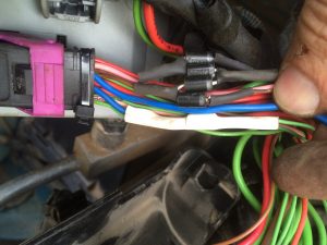
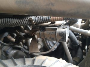
The engine cooling fan has two speeds that are controlled by two relays: T5 and T6. Only T5 is energized for low speeds, but both T5 and T6 are energized for high speed. For my manual switch I will only require the high speed setting, so it will need to energise both relays T5 and T6. To achieve this, I have broken into the wires coming out of Plug C (the black one) on the underside of the main engine bay fuse/relay box. Both of the wires are brown and marked with a cable identifier of ‘0000’ and come from pins 5 & 28 of the plug. To protect the ECU I have installed a couple of diodes between the ECU and the point at which I connect into the wiring loom. To be sure that I don’t affect the normal operation of the circuit when my switch is not activated, I have used a couple of diodes to connect to these two wires (see wiring diagram). The switch simply earths the two diodes which in turn energise the T5 and T6 relays, enabling the fan to come on at high speed.

Diodes for the fan
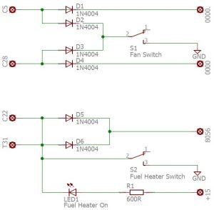
Circuit diagram
Fuel Filter Heater
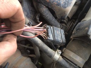
The two fuel filter heaters are controlled by relays T19 and T31. T19 is mounted in the main part of the engine bay fuse/relay box and its controlling wire also exits through Plug C, pin 22. This wire is green and has a cable identifier of ‘8056’. T31 is housed in the main body of the fuse/relay housing and also has a green wire with a cable identifier of ‘8056’. Both these wires are joined together much further up in the wiring loom. As this join is not easily accessible I have protected the ECU by adding two diodes at the points where I have cut into these two wires.
Diodes for the fan and T19 heater relay
T31 heater relay diode
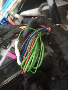
Wiring looms re-wrapped after diode insertion
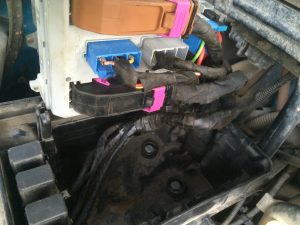
Rather than run new wires to this fuse/relay box, I decided to use some redundant wiring that is already in the vehicle. Attached below and at the front of the fuse/relay box is connector ST56 which is intended for an engine driven PTO.
ST56 below the engine bay fuse relay box
I cut the two wires ‘9135’ and ‘9136’ from pins 12 and 7, then pulled the wires back to the branch from the main loom. I then fed them down the main loom to the fuse/relay box where I used them to connect to the above two circuits.
Cutting the wires from ST56
Behind the central lower panel of the dash board are two relay holders. These sit on the end of cable looms without relays. Wires ‘9135’ and ‘9136’ are terminated in these relay terminals and are therefore easy to connect to with male spade connectors (these two wires also go to another connector which is for a PTO controller, but this is not installed so is not an issue). These relay holders also have earth terminals that I used for the switches.
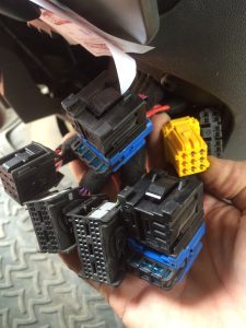
Some of the spare connectors behind the central panel!

Connections in the cab to the relay holders.
I also connected a LED to the fuel heater circuit so that I get a visual indication when the heaters are on (so I can see if I need to turn them on manually with the switch or whether the ECU has done it automatically).
Even though the ECU is protected by the diodes when the switches are activated, the ECU detects the relays being turned on. This generates a ‘SERVICE:’ ‘Check engine’ ‘Engine Failure 036’ for the fan (the EDC also turns off the air conditioning to maximise engine cooling) and ‘Engine Failure 114’ for the fuel heaters, plus the EDC light comes on. When the switches are turned off the faults will automatically clear themselves and the EDC light will go out. These are not ‘serious’ faults and so the engine does not go into ‘limp’ mode or employ any other restrictions.