
I noticed that the speedo seems to fail when driving through deep water and after washing the chassis. Every time I stopped to investigate it, the speedo would ‘fix’ itself, which made fault diagnosis very difficult. I had checked the connector on the sensor and the big connector on the chassis cable near the radiator ST120 – both were good. Finally, it failed completely!
Looking behind the dash board, I managed to track down connectors 142 and 144 (no markings as usual, thanks Iveco!). Normally they are connected together, but if you have a tachograph they will be plugged into it. The speed sensor’s power and signals go through these connectors, making them a convenient place to start my fault finding. I hooked up my PicoScope to see what was going on.
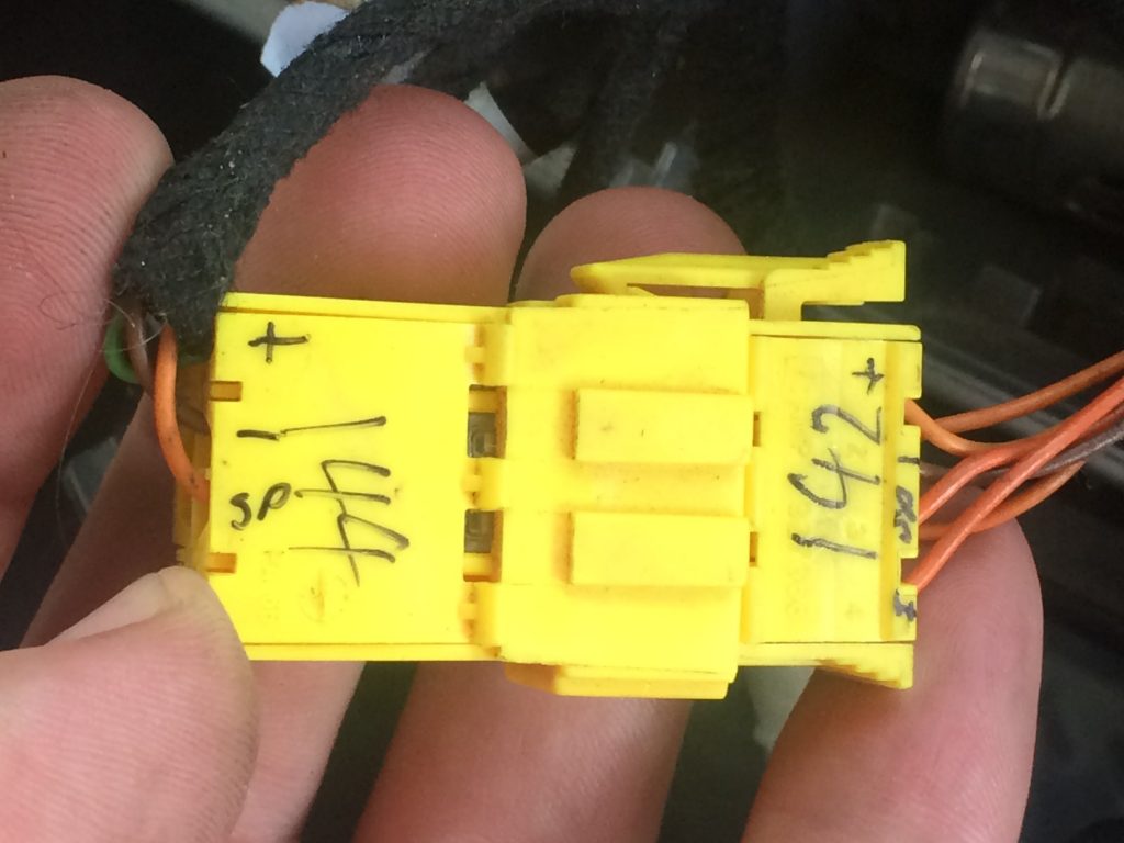
Ground and power were good, but there was no pulsing output on the speed signal or on the inverted signal wires. The speed signal did have an 8 volt bias. I disconnected the sensor and there was no change. I then disconnected ST120, the lower of the two big connectors by the radiator, and the bias voltage on the speed signal dropped to 5 volts (which is the voltage that I would expect – it’s probably from a pull up resistor in the Body Computer)! However, disconnecting that connector shouldn’t have caused any change in the voltage. Obviously, there was an issue in the chassis wiring.
Next, I tried waggling the wire in various places and was able to narrow the issue to the loom inside the chassis, in front of where the speed sensor wires come out of the chassis. It’s not easy to get in there, so I decided reluctantly to cut that wire at each end and run a new wire through. The wire had rubbed against another wire and scuffed through.
My fear was that there is almost certainly now some other system about to fail (ie the system of the other wire that was rubbing) but I have no idea which system this is! . Anyway, the wiring seems to be fixed for now, but unfortunately the speed sensor had died. I popped into the next Iveco dealer and they didn’t have any spare sensors. They phoned around, but it didn’t look like I could get a new one in a hurry.
For simple speed monitoring, I could drive using the GPS speed indicator. But there are some other issues associated with not having a functional speed sensor. First, without a speed feed, the ECU reduces power, which makes negotiating steep hills extremely slow-going. Also, exceeding 2500 rpm for more than a few seconds results in an engine warning 017 code (DTC 3411, OBD P0501, Vehicle speed sensor; A not plausible value compared to the engine working has been detected) and the engine reverting to full limp mode! This can only be cleared by stopping the engine, waiting a minute and starting again.
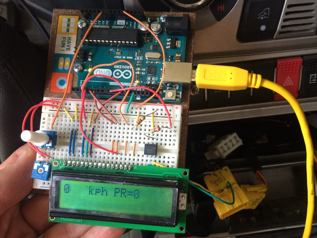
However, being a geek, I just happen to have an Arduino Uno computer and I set about writing a little program to simulate the speed sensor. I don’t have a GPS module for the Arduino, so instead I installed a control for me to set the speed on an LCD display. The Arduino then produces the frequency required to fool the Body Computer into thinking it’s getting a signal from the speed sensor. I tested it while parked and it worked well – I can set any speed I require on the speedo.
Having done all of that, I started thinking about where the extra voltage was coming from and which other system may have a damaged wire. I double checked the voltage on the 142/144 connectors: 12V. Then I checked the power pin on the sensor connector: 8.8V. When I split the cable at ST120, it was 12V. From this it seemed that the power cable between the ST120 socket and the sensor is damaged, and this is probably where the extra voltage on the signal cable had come from. I ran a new sensor power cable from ST120 to the sensor socket and… success! It’s all working again. Basically, the sensor power and signal wires had rubbed together and were shorting together in the chassis rail.
As a side note to all this, here’s my chip-in on the Iveco Daily 4×4 wiring…. Anyone who knows anything about electronics and noise management will know that the reason for having a signal together with an inverted signal, is so that the inverted signal can be inverted at the receiving end and added to the normal signal. This way, the noise on the inverted signal cable is also inverted and cancels out the noise on the normal signal cable. To make this most efficient, the signal and the inverted signal cables should be twisted together so that they are subjected to the same noise (check out your computer or router’s CAT6 network cable – they’re all twisted-pairs for this reason). Iveco don’t seem to have taken this standard electronics practice on-board! In my Iveco truck, the signal wire is twisted with the power wire, and the inverted signal is twisted with the earth wire. Chuffing useless!!!! Anyway, at least I now know that it was the power and the signals wires rubbing together that caused all the problems.
Here is the software I wrote for the Arduino Uno:
// Program to temporarily replace the speed sensor
// Having had a vehicle speed sensor failure and no spares being available
// I decided to use the Arduino to produce a signal to simulate the sensor.
// This will require the passenger to use the control to set the vehicles GPS
// speed on the LCD display.  The Arduino will then produce the correct frequency
// of pulses for the truck to calculate the speed.  This will prevent the truck from
// producing an error message and going into limp mode.  It will also make the
// speedometer and milometer function (based on the manually input speed).
// www.tuckstruck.net

#include <LiquidCrystal.h>
LiquidCrystal lcd(12, 11, 5, 4, 3, 2);
int const manualInputValue = A0;  //this is the control for setting the vehicle speed
int vehicleSpeed;
int pulseRate;

void setup() {
  lcd.begin(16, 2);
  lcd.print("Speed Sensor");
  lcd.setCursor(0, 1);
  lcd.print("Replacement");
  delay(1000);
  lcd.clear();
  lcd.setCursor(0, 0);
  lcd.print("www.");
  lcd.setCursor(0, 1);
  lcd.print("tuckstruck.net");
  delay(2000);
}

void loop() {
  vehicleSpeed = (analogRead(manualInputValue) / 10.23);
  lcd.clear();
  lcd.setCursor(0, 0);
  lcd.print(vehicleSpeed);
  lcd.setCursor(4, 0);
  lcd.print("kph PR=");
  pulseRate = (vehicleSpeed * 231.316726);
  //231.316726 is the number of pulses a second the sensor should produce at 1 kph with 255/100R16 XZL tyres
  lcd.print(pulseRate);
  lcd.setCursor(0, 1);
  if (vehicleSpeed >  20 && vehicleSpeed < 25) {
    lcd.print("*");
  //the increasing number of *** help the user see how fast they are adjusting the speed control
  }
  if (vehicleSpeed >= 25 && vehicleSpeed < 30) {
    lcd.print("**");
  }
  if (vehicleSpeed >  30 && vehicleSpeed < 35) {
    lcd.print("***");
  }
  if (vehicleSpeed >= 35 && vehicleSpeed < 40) {
    lcd.print("****");
  }
  if (vehicleSpeed >  40 && vehicleSpeed < 45) {
    lcd.print("*****");
  }
  if (vehicleSpeed >= 45 && vehicleSpeed < 50) {
    lcd.print("******");
  }
  if (vehicleSpeed >  50 && vehicleSpeed < 55) {
    lcd.print("*******");
  }
  if (vehicleSpeed >= 55 && vehicleSpeed < 60) {
    lcd.print("********");
  }
  if (vehicleSpeed >  60 && vehicleSpeed < 65) {
    lcd.print("*********");
  }
  if (vehicleSpeed >= 65 && vehicleSpeed < 70) {
    lcd.print("**********");
  }
  if (vehicleSpeed >  70 && vehicleSpeed < 75) {
    lcd.print("***********");
  }
  if (vehicleSpeed >= 75 && vehicleSpeed < 80) {
    lcd.print("************");
  }
  if (vehicleSpeed >  80 && vehicleSpeed < 85) {
    lcd.print("************#");
  //I normally cruise at about 80 kph so put a # in to make the adjustment to this speed quicker
  }
  if (vehicleSpeed >= 85 && vehicleSpeed < 90) {
    lcd.print("************#*");
  }
  if (vehicleSpeed >  90 && vehicleSpeed < 95) {
    lcd.print("************#**");
  }
  if (vehicleSpeed >= 95)                      {
    lcd.print("************#***");
  }
  tone(8, pulseRate, 1000);
}