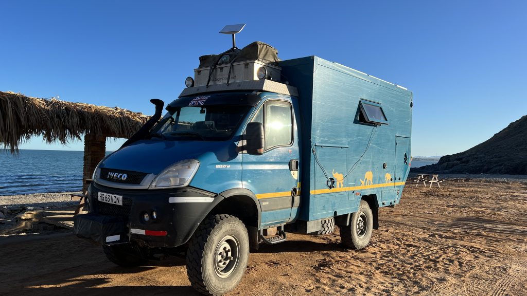
Unlimited, high-speed, satellite-based internet access at a reasonable price. Sounds great, eh? Elon Musk’s SpaceX Starlink geekery promises all this in the near future. We investigated what it is, how it works, and why it might (or might not) be suitable for overlanders and life in an RV (Starlink for Overlanders). But being a geek1 and having a bit of lock-down time on my hands, I decided to do a full installation of the Starlink system into our Cuthbert. Here’s how I went about installing Starlink in an RV / overlanding truck.
For the sake of completeness, this blog overlaps slightly with our original ‘Starlink for Overlanders’ so please forgive a bit of repetition here.
- Starlink Kit – Basic Set-up
- Looking after Dishy
- Installing Starlink in an RV / Overlanding Truck
- Geek Info – System/Equipment Data and Specs
- Update No. 1 – Dishy under table-top storage and cable shortening
- Update No. 2 – Slow ethernet connection and reduced power
- Update No. 3 – Modifying the Starlink Power Supply to run on AC and DC
- Update No. 4 – Starlink Mobile Roaming
- Update No. 5 – Rectangular Dish
- Update No. 6 – Cable Retention Collar
- Update No. 7 – Tp-link Archer AX50 (AX3000) Router Installation
- Update No. 8 – Dish RJ45 socket modification
- Update No. 9 – Gen 3 Starlink Installation
If you sign up for Starlink with our referral code (click here), we will each receive one month of free service 30 days after activation. For more information on how it works, check out Starlink support topics here.
Starlink Kit – Basic Set-up
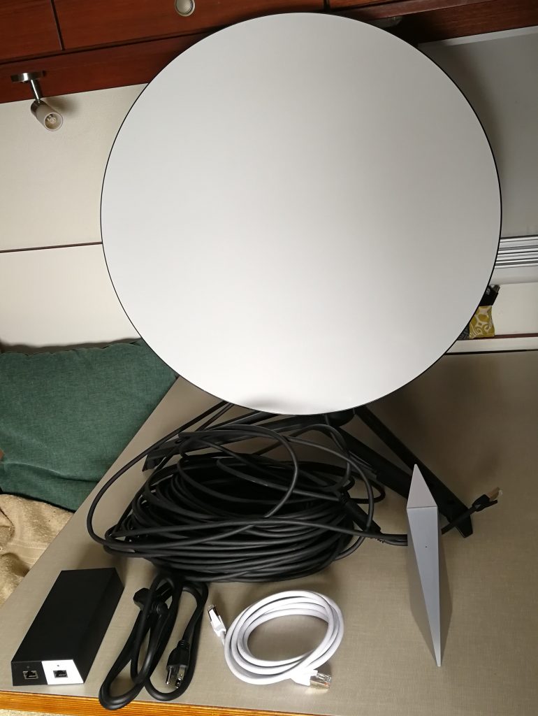
A Starlink kit consists of:
- ‘Dishy McFlatface’ – yes, that’s what SpaceX actually calls it, or ‘Dishy’ for short;
- a tripod-stand for Dishy;
- a power-supply, router and connecting wires
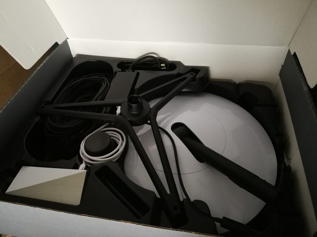
In the box when it arrives, Dishy is already wired-up and plugged-in to its power-supply and the router, so the setup process is extremely simple:
- pull Dishy out of the box
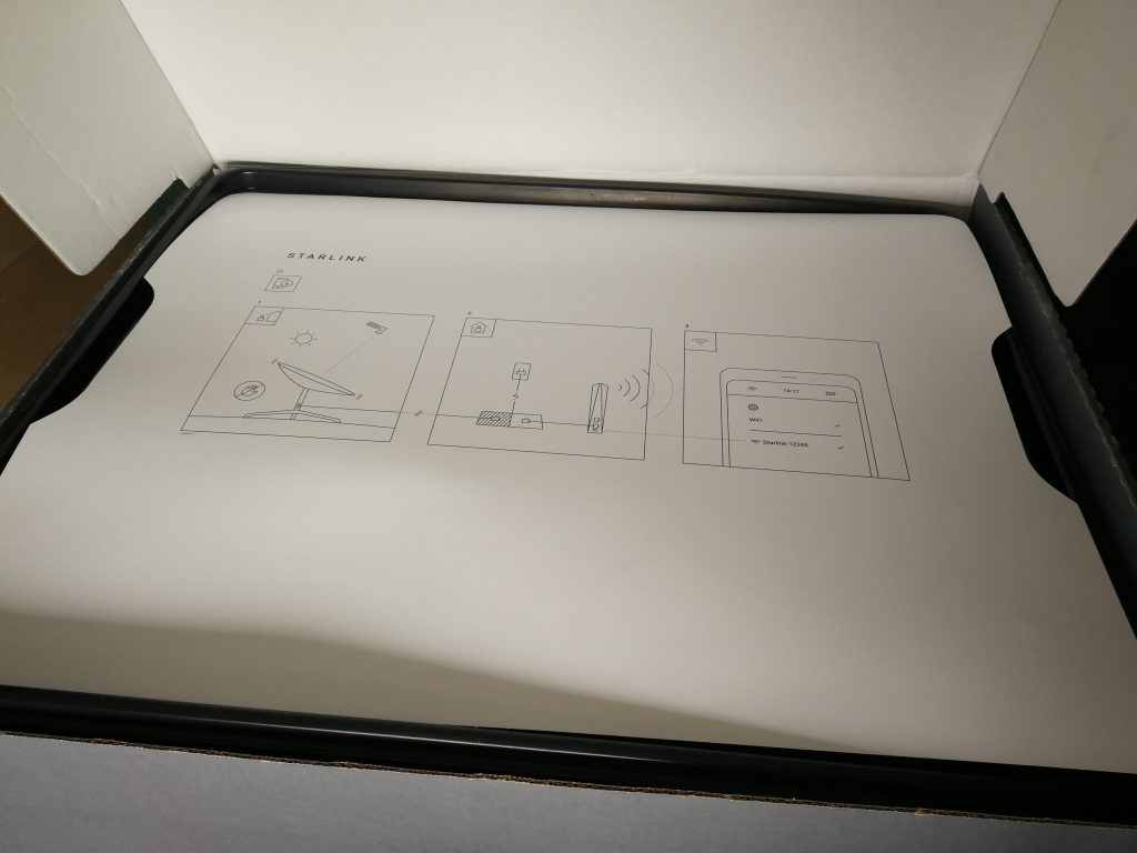
- put Dishy on the tripod outside in a spot with a good view of the sky (see below ‘Mounting and Locating Dishy’)
- Plug-in to mains power. Dishy will now start connecting to the overhead satellites and the router will power-up.
- Use the Starlink app to set up the router’s Wi-Fi name and password, then you can log-in and surf away on the inter-web!
Mounting and Locating Dishy
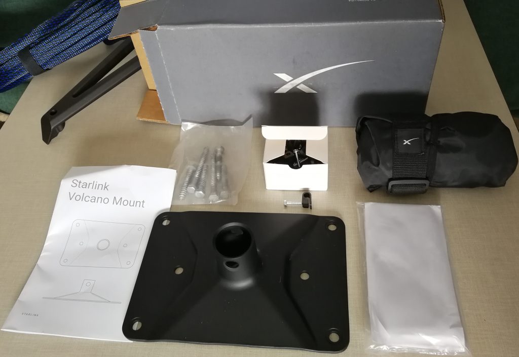
Dishy comes with a tripod stand in the box and a 100’/30m cable so that it can be mounted and placed in a location that has good visibility of the sky. Alternatively, it can be mounted on a choice of optional extra accessories: a ‘Volcano mount’ (US$25 + tax, April 2021) that can be bolted or screwed to a flat surface; or the ‘Pipe Adapter’ (US$25 + tax, April 2021) that allows Dishy to be fitted to various diameter poles.
To find the best position for Dishy you need to download the Starlink app onto your phone (iPhone or Android). The app uses your phone’s camera and position sensors to look for any obstructions. As you move the phone around looking at the sky, it highlights the area of the sky for your location that needs to be obstruction free and indicates the best position for Dishy.
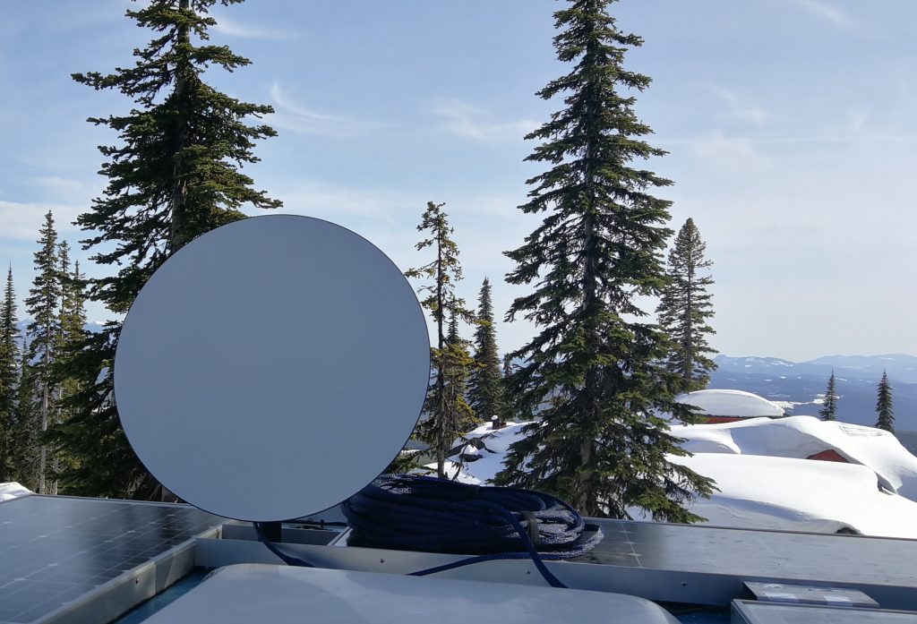
For overlanders, it would be convenient to have a Volcano mount on your vehicle roof that can be used if you are parked-up in a good location (see below Installing the Volcano mount). If the vehicle isn’t parked in a location that is good for satellite reception – maybe in a shady place under trees – you can put Dishy on the tripod up to 30m away from the vehicle. Note: Dishy is not designed for very high wind-speeds, so it should be taken down from the Volcano mount and stowed away before driving.
A user asked the Starlink support team (on Reddit) if there would be an issue mounting Dishy 80’ up a tree. Their reply was that if Dishy did not move more than 3’ it would be fine! This equates to a movement of about 2 degrees, which is quite a lot. This is encouraging for overlanders. With Dishy mounted on the roof of a vehicle, it will work well even with slight vehicle movements (e.g. rocking in the wind or while people move around inside).
Looking After Dishy
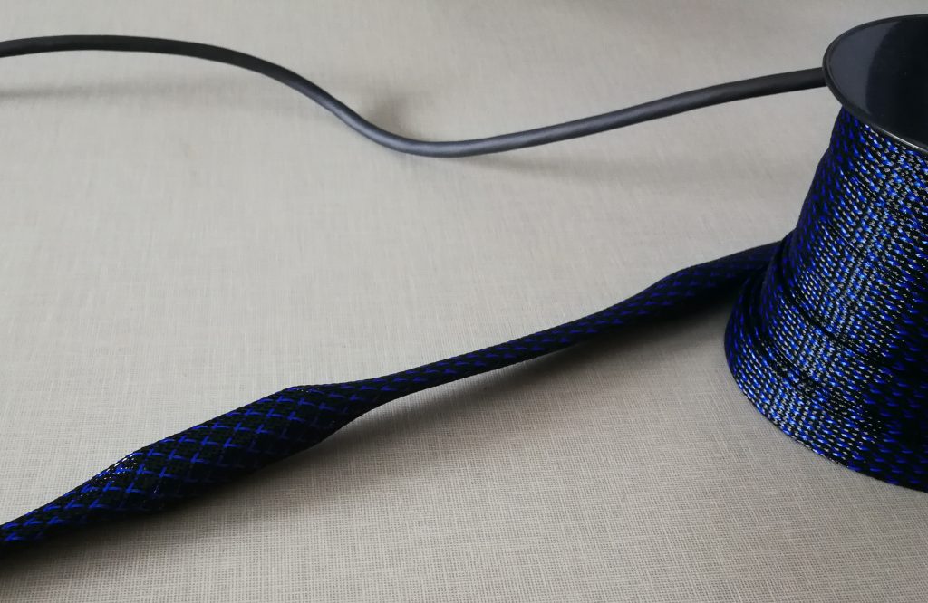
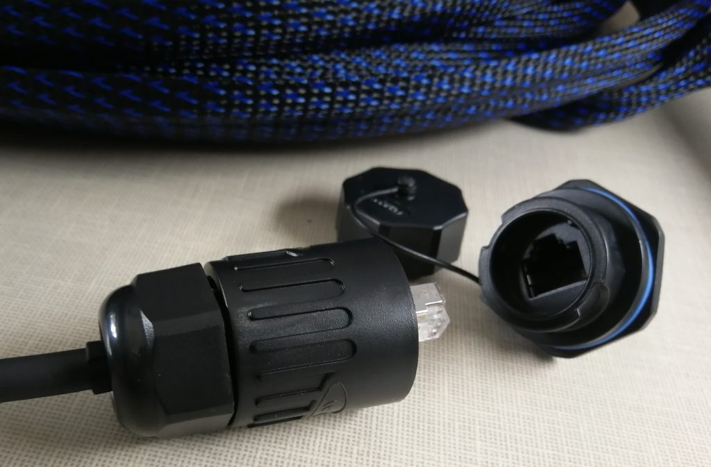
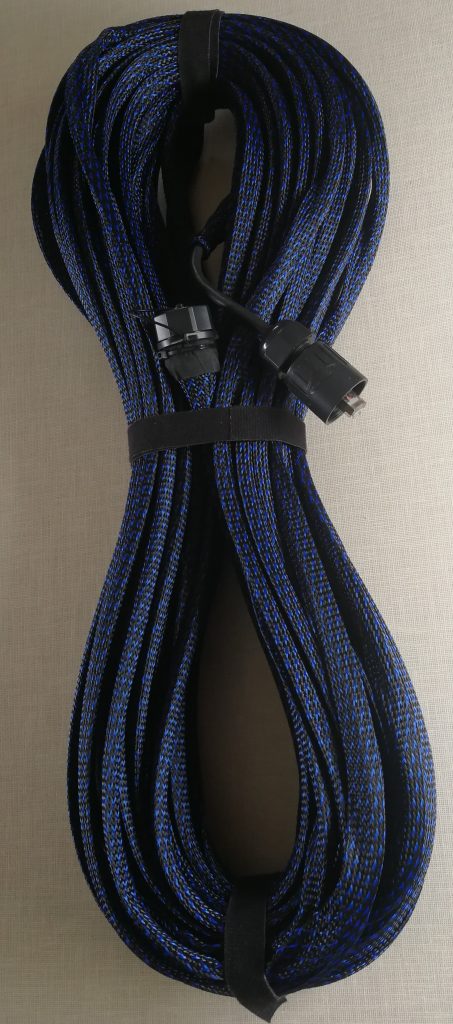
To help protect Dishy’s cable from wear and tear I have put some ¾” expandable braided sleeving over it. You need expandable braid that will expand over the 22.8 mm (Dishy end) and 19.5 mm plug end ferrite cores on the cable, the ¾” braided sleeve did this easily. You can get versions of this expandable braid that has a coating to repel rodents, so they do not chew through the cable if it is laid on the ground.
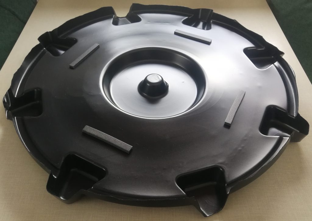
To protect Dishy’s face, I cut-out the inside of the packaging that the Starlink system came in. This allows us to put Dishy face-down in the packaging while we travel and prevents damage to the phase array.
Installing Starlink in an RV / Overlanding Truck
No ‘installation’ is necessary with Starlink. You could of course just get it out of the box and run loose wires from the router and the power-supply (inside) to Dishy (outside) whenever you want to use it. However, I decided to instal the system more permanently into our Cuthbert so as to:
- avoid having to open a window/door/mosquito net to accommodate the cable running outside to Dishy;
- tidy-up loose cabling; and
- simplify/speed-up the set-up/pack-up of the Starlink system.
With this installation, all I have to do to setup the Starlink connection is put Dishy on his tripod outside (or Volcano mount on the roof – see above) and plug in Dishy’s data cable to a plug on the roof or in a lower locker. Inside Cuthbert, I simply switch on the inverter and the power switch for Starlink.
Installing Dishy’s power-supply
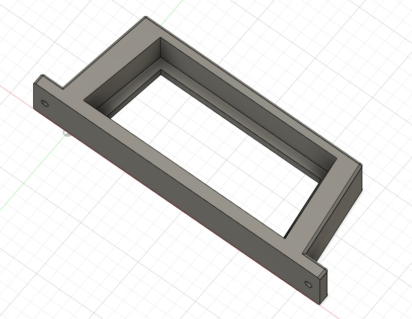
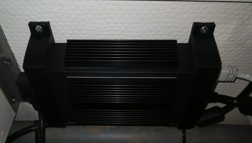
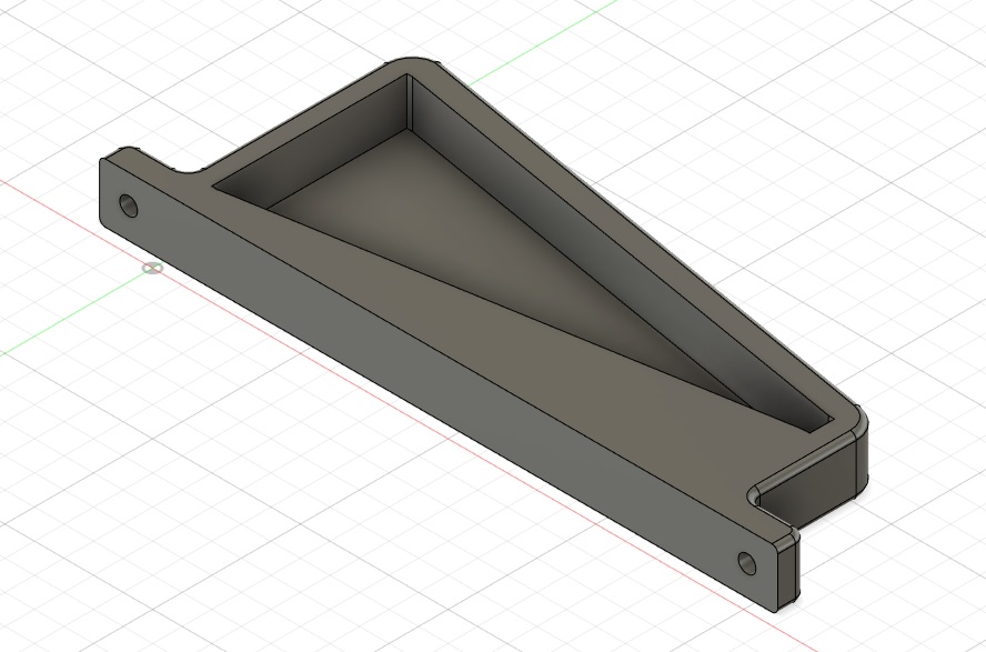
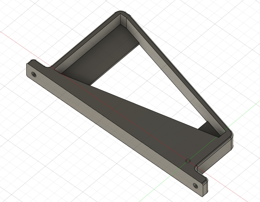
I mounted the power-supply on the wall in the electrical equipment cabinet inside Cuthbert. For a bespoke fit, I designed a bracket of exactly the right size and was lucky enough to have a friend produce my design on his 3D printer. The two brackets hold the power-supply at each end and spaces it 5 mm from the wall. This allows ventilation around the power-supply for cooling. Obviously having the bespoke mounting bracket is an unnecessary little feature that I have added (just because I could 😉) but wherever you decide to house it, take care to allow some room around it to allow for the cooling. To help with the cooling, I have also added a few stick-on heat sinks onto the power-supply. The mains power cable is wired to the inverter through a power switch which is accessible outside the cabinet.
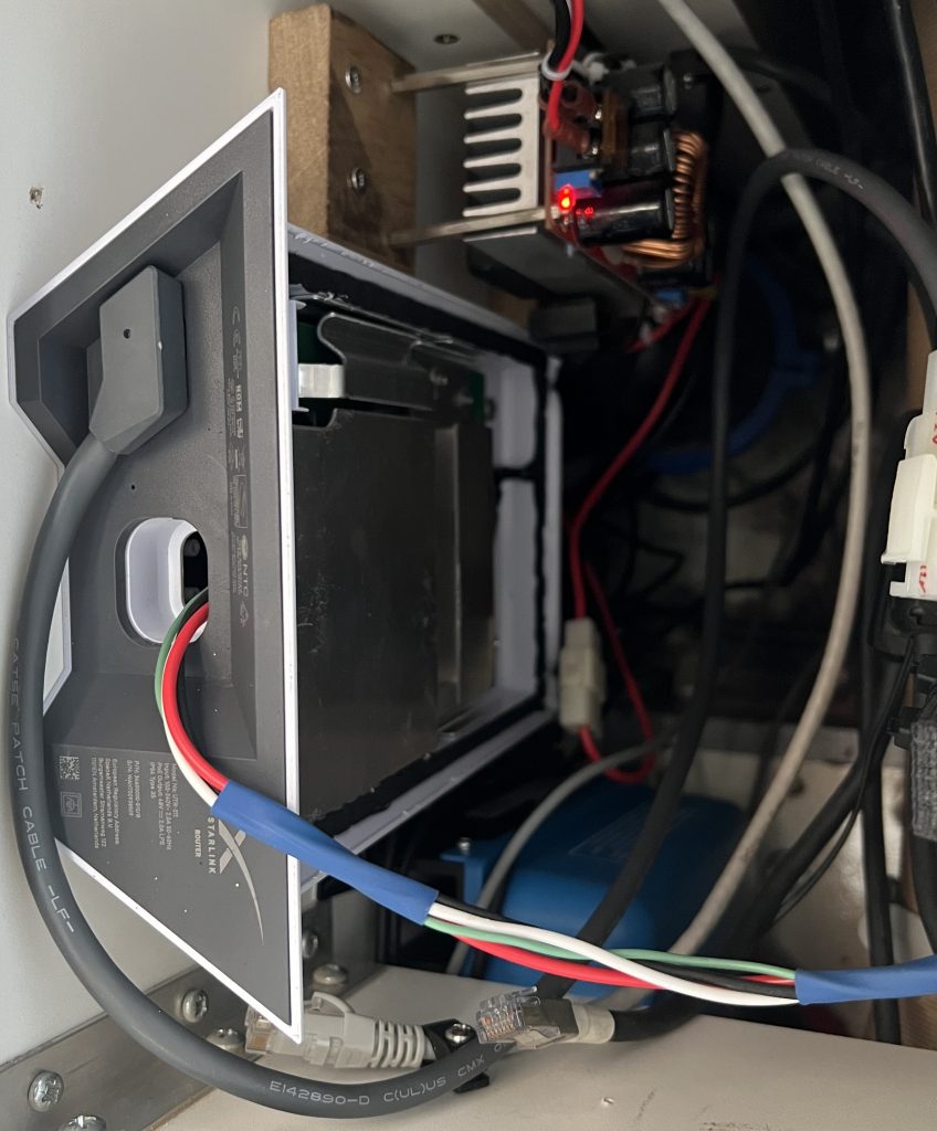
Installing the Router
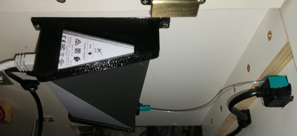
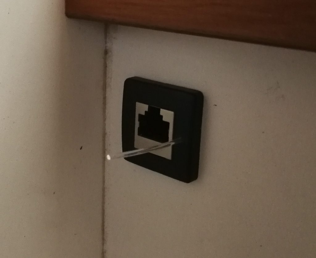
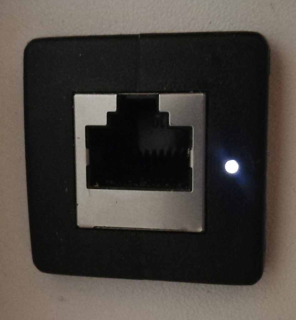
I also mounted the router on the wall in the truck’s electrical equipment cabinet alongside the power-supply (as with the power-supply, this is mounted with bespoke brackets that I designed and had produced by a friend on his 3D printer, but it’s obviously not necessary to have this). I have mounted the router up-side-down so that the reset button is easily accessible. I have added a panel mounted RJ45 socket that attaches to the AUX port of the router. This allows me to easily plug in my computer without accessing the cabinet where the router is installed. I have also attached a plastic optical fibre over the router LED and installed it through the side of the panel mounted RJ45 socket moulding so the LED can be monitored without opening the cabinet.
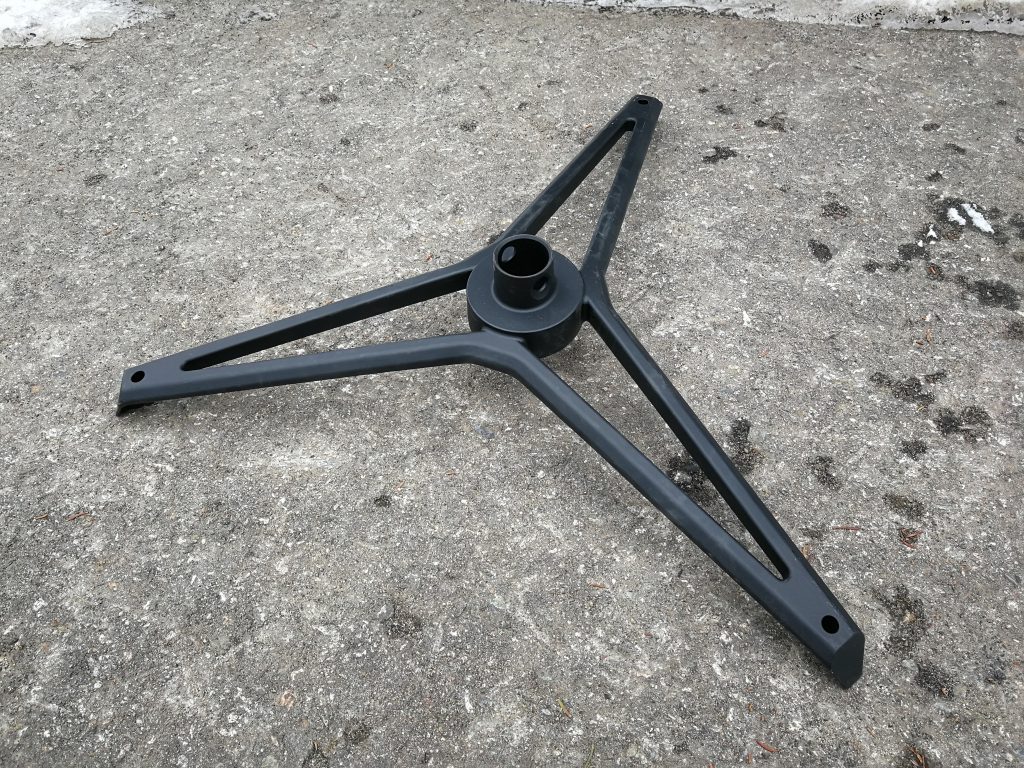
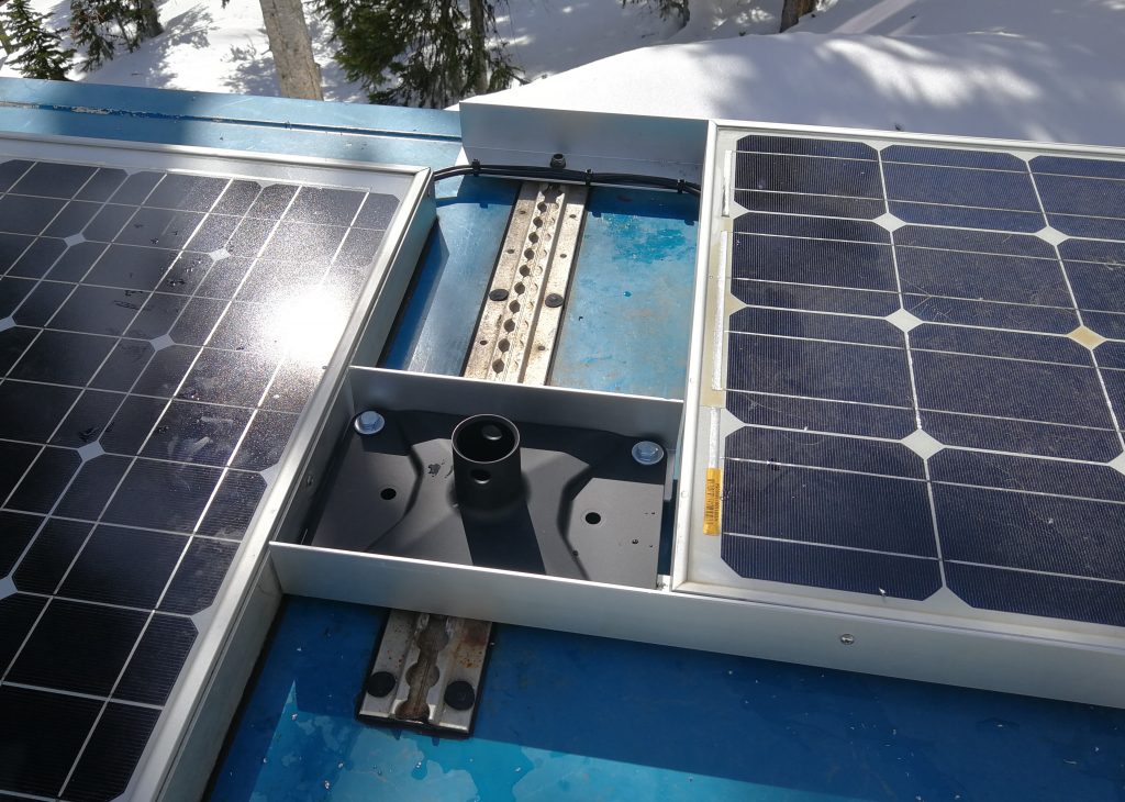
Installing the Volcano Mount
I have installed the Volcano mount in a position on the roof that is easily accessible from inside the truck by the roof-hatch. Dishy is not designed for high wind-speeds (from the Regulatory Notices2: ’Mounts are not designed for hurricane/tornado wind loads’) and so presumably it would also not cope well with the dynamic loads experienced while braking. It should therefore be taken down from the Volcano mount and safely stowed away before driving.
The Regulatory Notices also say that ’During normal operation to avoid possibility of exceeding the FCC/Industry Canada radio frequency exposure limits, this equipment should be installed and operated with minimum distance of 28 cm (11 inches) between the radiator and your body’ so the roof-top is a good option for us as the dish is more than 28 cm (11 inches) above the volcano mount when in operation.
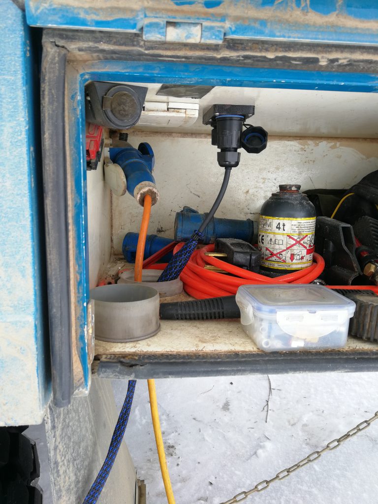
Installing Data/Power Sockets
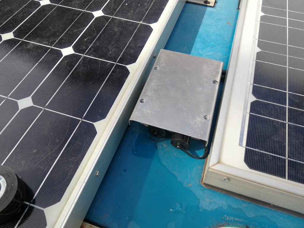
As noted above, when Dishy is set-up outside either on the tripod or on the roof-top Volcano mount, you can simply connect Dishy to the power-supply and router mounted inside the truck, by running a loose cable outside from Dishy. However, to avoid having to open a window/door/mosquito net to accommodate the loose cable, I installed fixed external waterproof sockets: one socket on the roof next to the Volcano mount, and another at ground level (in an external locker). With these, Dishy can be quickly/easily ‘plugged in’ when we arrive at our camp spot.
First, I needed extension cables for the PoE data cable between the power-supply and the external sockets. The Regulatory Notices say: ’To maintain compliance with FCC Rules and Regulations, connections to this device must be made with shieled cables have metallic RFI/EMI connector hoods.’ I have therefore used good quality screened Cat 8 ethernet cables. Given the high power of the PoE, I decided to use data cables of at least 24 awg to minimise any voltage drop. I believe others have found 24 awg to be okay for up to an additional 50’/15 m. If you extend Dishy’s PoE data cable by more than 50’/15 m, you will need a larger 23 awg (or bigger) cable to reduce the voltage drop, otherwise Dishy will stop working.
Once the external sockets and their extension cables are in place, the ‘easy’ way to connect Dishy is to simply plug the relevant extension cable (i.e. the extension from either the roof socket or the ground level socket, whichever is being used) into the power-supply by plug. However, I have seen reported that constant plugging/unplugging into the power-supply can lead to poor connectivity with plug pins breaking. I therefore wanted both external sockets to be connected to the power-supply at once. This would allow me to plug Dishy into either of the external sockets and no wiring would need to be changed or switched over at the power-supply.
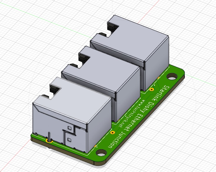
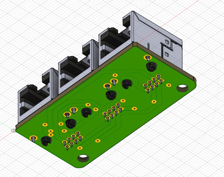
Unfortunately, I could not find a commercially available device for joining two RJ45 plugs of the PoE data cables into one (without reversing the data lines or that could handle the power) so I designed and made my own. For those of an even more geeky disposition who want to make their own, read on below in the ‘Top-geekery Bonus Installation Section‘: Jointly connecting both external sockets to the power supply…
Jointly connecting both external sockets to the power-supply
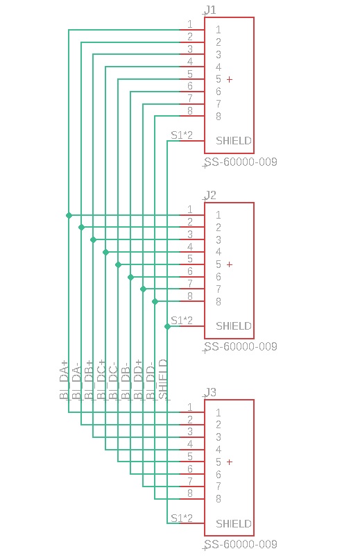
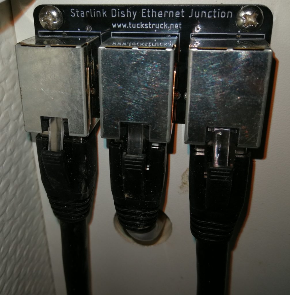
With this installation, Dishy can be plugged into either of the external sockets and no wiring needs to be changed or switched over at the power-supply. Unfortunately, I could not find a commercially available device for joining two RJ45 plugs of the data cables into one (without reversing the data lines or that could handle the power) so I designed and made my own. I chose 1.5 mm wide PCB tracks to easily handle the power. Obviously nothing else should be plugged into the unused socket.
See Update No. 2, we are no longer using this connector
Here is my design of the circuit and PCB in Eagle:
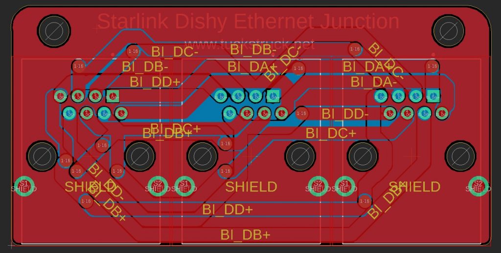
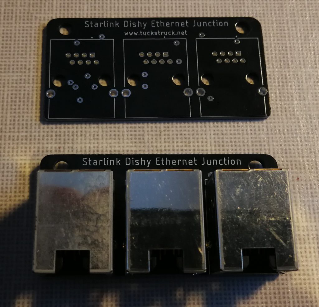
The waterproof plug, socket and the PCB RJ45 socket that I found are only rated to 1.5 amps and not the 1.6 amps of the power-supply. The 1.5 amps rating would provide a maximum power of (1.5A x 56V = 84W x 2) 168 Watts, which is more than the peak power of 159 Watts I have observed to date. Therefore, I am happy that the 1.5 amps rating will be fine.
Dishy has some large ferrite cores on its data cable, presumably to reduce RF noise from Dishy. I have added similar but smaller ferrite cores at both ends of the patch cords that I have added between the waterproof sockets and the power-supply and one in the middle of the patch cord from my PCB to the power-supply The PCB is fixed inside the cabinet near the power-supply.
Here are links to the parts that I used:
- PCBs were made by Seeed Studio: https://www.seeedstudio.com/fusion_pcb.html
- 24 awg data cables from here (available in various lengths): https://www.amazon.co.uk/Monoprice-Cat8-Ethernet-Network-Cable-Black/dp/B07G9Q74ZZ
- Waterproof RJ45 data connectors from here: https://www.amazon.com/CERRXIAN-Femle-Female-Waterproof-Connector/dp/B07D49D4FF
- RG47 sockets used on the PCB are from here: https://www.digikey.ca/en/products/detail/stewart-connector/SS-60000-009/1033363
- Ferrite ring cores from here: https://www.amazon.co.uk/DGQ-Felt-Furniture-Pads-Non-Slip/dp/B00V4MMIBW
- Expandable braided sleeving from here: https://www.amazon.ca/100ft-Expandable-Braided-Sleeving-BlackBlue/dp/B075VRJNXQ
- Panel mounting LAN socket and cable from here: https://www.amazon.co.uk/Cerrxian-3-28ft-Female-Ethernet-Network/dp/B01MY04R2N
- Plastic optic fibre: https://www.amazon.co.uk/3-28ft-plastic-cables-ceiling-0-06in/dp/B01MRLSCC2
Geek Info – System/Equipment Data and Specs
Okay… you really don’t need to know this stuff. But here’s a bit more tech detail:
The Starlink Constellation
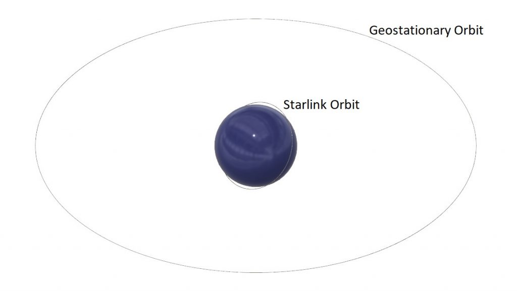
As mentioned above, Starlink by SpaceX is a constellation of low-earth orbit satellites (approx 550km above the earth – much lower than a geo-stationary satellite) with the advantage of a low-latency satellite connection. The constellation is designed to use 12,000 satellites and SpaceX has developed an ‘affordable’ launch system that will see the deployment rate increase rapidly over the coming months.
Once they’re all launched, the satellites are going to be arranged in several overlapping ‘shells’. SpaceX’s latest plan is for an initial deployment of 4 shells, the first of which will contain 1,584 satellites at an orbital inclination of 53.2 degrees (the satellites will travel north and south of the equator to a latitude of 53.2 degrees). They also plan on shells with orbital inclinations of 70 degrees and 97.6 degrees to provide global cover by the end of summer 2021. Additional shells will be added over these to increase the capacity of the network as more users come online. As at 7 April 2021, SpaceX already have 1,378 operational satellites in the first shell, ten in the 97.6 degree shell which are providing the ‘beta service’ for internet.
Note: all equipment dimensions noted below were measured in mm and converted to inches
Dishy – Data and Specs
- Diameter 23.2”, 589 mm
- Height with mast 25.4”, 645 mm
- Thickness when stowed 7” 178 mm
- Mast diameter 1.4”, 35.6 mm (the section that plugs into the mountings)
- Dishy weight 12 lbs, 5.4 kg
- Cable weight 3.5 lbs, 1.6 kg (cable is not detachable from Dishy end)
- Cable length 100’, 30m
- Ferrite cores:
- Dishy end, 0.9” 22.8 mm diameter 2.3” 59 mm long
- Plug end, 0.8” 19.5 mm diameter, 2.2” 55 mm long
- Cable 0.3” 6.9 mm diameter
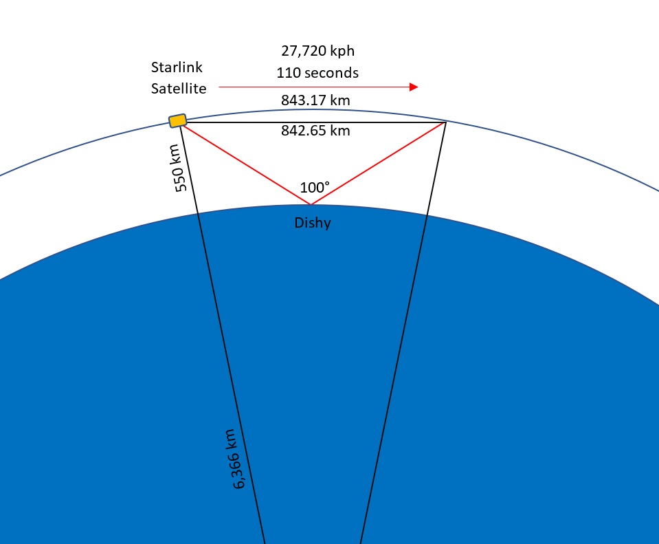
Normally when a satellite dish is set up, it needs to point extremely accurately. Moving a satellite dish by just one degree will move the beam by 642 km at a geostationary satellite! Dishy however, is using low-earth orbit satellites, so one degree of movement only moves the beam by 9.6 km at the height of the satellite.
But of course, it’s not quite as simple as that. Geostationary satellites are – as their name implies – stationary (well, they’re orbiting at a speed of 11,052 kph, so as the earth rotates, they appear stationary to us on earth). Low-earth orbit satellites are moving at approximately 27,720 kph, so Dishy needs to track the satellites as they fly overhead. By my calculations the longest a Starlink satellite will be visable to Dishy is only 110 seconds! Luckily, Dishy is not like your every-day, conventional satellite dish. Dishy is a phase array!
A phase array antenna is a very clever device. Rather than using one transmitter and receiver, it uses a lot of transmitters and receivers that can be controlled individually. In the case of Dishy, it has about 1,444 individual transmit/receive cells spaced half a wavelength (transmission frequency) apart.
λ = v / f
v = speed of radio wave in air = 299,792,458 m/s
f = Tx frequency = 14.25 GHz
λ = Tx wavelength = 0.021 m = 21 mm
Half wavelength spacing = 10.5 mm
If you imagine having two transmitters next to each other spaced half a wavelength apart and they both transmit at the same time the signal from the two transmitters will cancel each other out to the sides (due to the half wavelength spacing between them) and the signals will combine straight ahead. If you now multiply this across a large array you can get a very directional pencil beam. Now rather than transmitting at the same time, you change the transmission time slightly between adjacent cells. The way the transmission waves interfere with each other will change slightly. This will tend to cause the resultant beam to move towards the side that transmitted last. In school during a physics lesson you may have seen this effect when you dropped a small stone into water and saw the ripples on the surface, then dropped two stones into the water and saw the interferance pattern between the ripples.
Dishy does not transmit pulses, it transmitts a continuous wave, so to achieve the same effect as delaying transmission time between pulses it changes the phase of the transmission between adjacent cells to create the beam steering effect (this is a simplification, but hopefully the analogy above helps you visualise what is going on). This change in phase changes the direction that Dishy transmits and can be controlled in both azimuth and elevation. The same principle can be applied to the receivers which allows dishy to ‘listen’ in specific directions too. This is called ‘electronic beam steering’ and means that Dishy does not need to physically move. Without moving, Dishy can see ±50 degrees off the centreline of its face, in both azimuth and elevation. It also means that Dishy’s beam can be steered almost instantaneously from one side to the other, something a conventional dish could never achieve.
With a ±50-degree beam capability, Dishy can see a 100-degree wide cone of the sky. That’s wide, but unfortunately not quite wide enough. During the initial roll-out of Starlink, satellites may need to be used that are only 25 degrees above the horizon (as the constellation grows, satellites less than 40 degrees above the horizon will not need to be used), but Dishy has a solution to this. When Dishy is powered up, the first thing it does is point straight up. It has a couple of small electric motors within the antenna so it can adjust the dish’s position. Dishy is clever and has some level sensing devices (just like in your phone). This means that when Dishy is set up, its mast only needs to be within 40 degrees of vertical. The on-board sensor will automatically find level and point the dish straight up. This is perfect for a quick setup at a camp-spot or if you put it on the roof of your rig it does not matter if you are not parked level.
Once it is level, Dishy will get a GPS fix and scan the sky to listen for Starlink satellites. Once it has worked out its position and where the nearest Starlink satellites are transiting past, it will turn and tilt to optimise itself for electronic beam steering. Once in this position, it will not move again until you tell it to ‘stow’ in the App when you come to pack it up. In the northern hemisphere, Dishy will generally tilt to the north and in the southern hemisphere to the south. This is to optimise reception and partly to avoid the dish from pointing towards any geostationary satellites that could be affected by the Starlink as it shares some of the same frequencies (Tx 14 GHz to 14.5 GHz and Rx 10.7 GHz to 12.7 GHz). See update #8 on Starlink Mobile Roaming for latest information.
Bonus geek data, the 3dB (half power) beam widths:
- Tx bore sight 2.8°
- Rx bore sight 3.5°
- Tx slant 4.5°
- Rx slant 5.5°
Power-Supply – Data and Specs
- Height 1.4” 35 mm x length 6.3” 160 mm x width 3.4” 87 mm at bottom, 23” 75 mm at top
- Weight 1.1 lbs 0.5 kg
- Input, 100 to 240 VAC ~ 2.5 A 50 to 60 Hz
- PoE output 1b, 56 VDC 1.6 A (89.6 W)
- PoE output 2, 56 VDC 0.3 A (16.8 W)
- Total maximum output 180 W
The power-supply is of a switch mode type. Just like many laptop computer power supplies, it can accept an input of 100V to 240V AC, 50 Hz to 60 Hz. It provides Power Over Ethernet (PoE) through the data cables to Dishy and the router. The power supplies maximum output to the router (white port) is 56V DC at 0.3 amps and to Dishy (black port) two feeds of 56 V DC at 1.6 amp each.
The maximum power of the power-supply is 180 watts, but from my observations the average power draw is about 99 watts with power fluctuating between about 87 watts and 159 watts (the coldest we have tested to is -5C (23F), in colder conditions the peak power may be higher). The PoE output to the router will detect if a non PoE router is attached and will not turn on PoE if it is not required. This means that non-Starlink routers or your computer can safely be attached. Comments on Reddit have reported that the power-supply will not work on non ‘pure sine wave’ inverters.
Operating the power supply mounted in my designed 3D printed brackets from our 230V pure sine wave inverter with the stick-on heat sinks has produced a maximum temperture of 46.7C (116F), but we have not operated it below -5C (23F) in snowy conditions where it may use more power to clear the snow.
Router
- Height 7.4” 188 mm x top triangle 1.3” 33 mm x 3.3” 85 mm, bottom triangle 3.5” 88 mm x 1.9” 48 mm, the triangles are rotated 180 drees from each other
- Weight 0.9 lbs 0.4 kg
- PoE input 56 VDC 0.18 A
The router is PoE through the data cable and provides 2.4 GHz and 5 GHz Wi-Fi. There is also an Aux port to attach a computer directly. The administrator side of the router is not accessible . Many people seem to have used their own routers, rather than the one provided by Starlink. There are a few technical issues with doing this, but there are work-arounds if you understand routers. Some have reported faster speeds using the Starlink router rather than a third party router, others the opposite, but the Starlink router is more than adequate for our use and being PoE does not require another power supply. Connecting to the AUX port could provide higher data rates then connecting through Wi-Fi.
Tripod
- Leg length from centre 13”, 330 mm
- Height 4” 102 mm
- Peg/screw down holes in the end of the legs are 1.25” 32 mm from the end of the leg
- Peg/screw down hole diameters 0.375” 9.5 mm
- Weight 2.4 lbs 1.1 kg
Volcano Mount
- Height 3” 76 mm x width 6.2” 157 mm x length 9” 230 mm
- Weight 0.7 lbs 0.3 kg
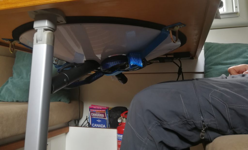
Update No. 1: 7 May 2021
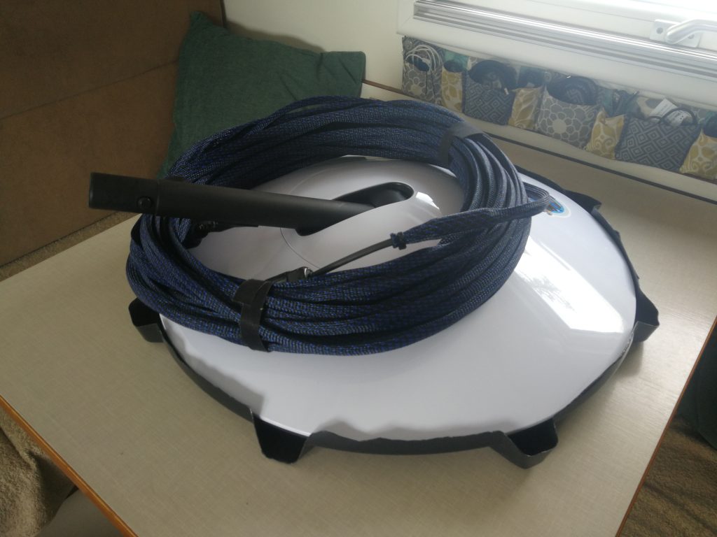
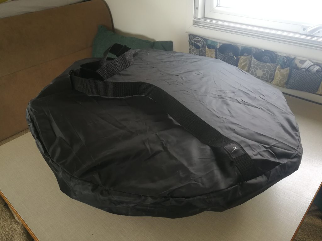
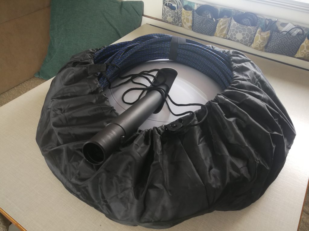
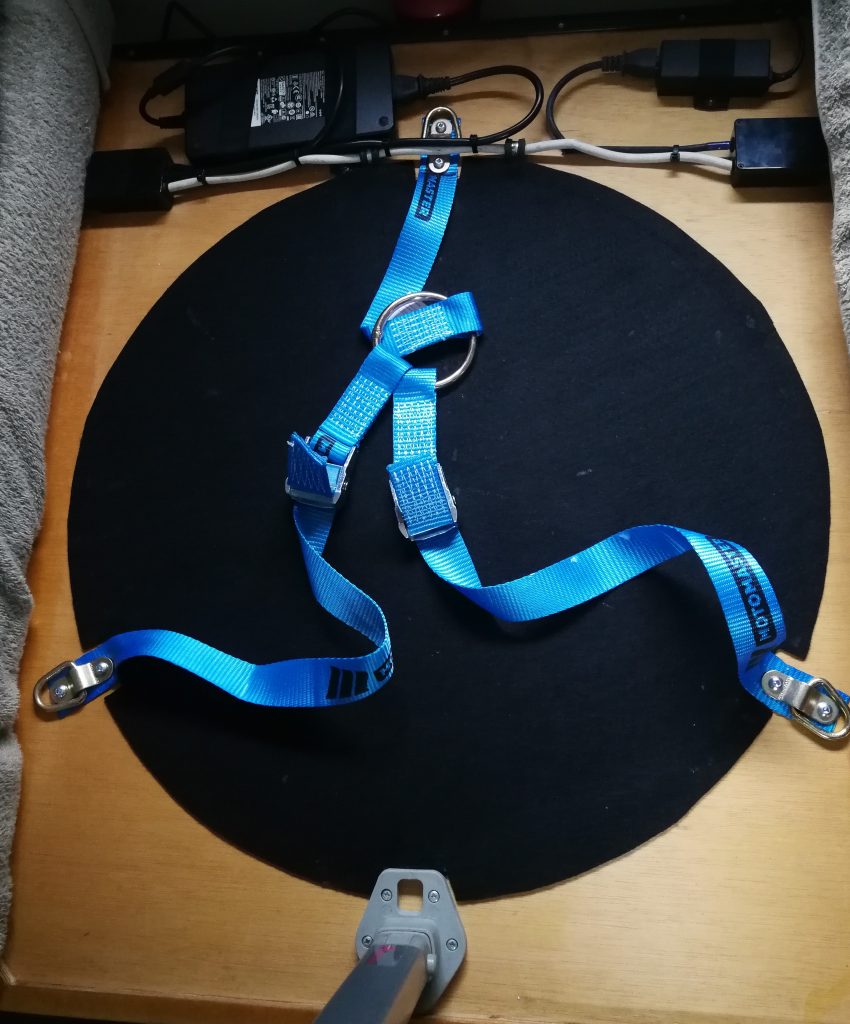
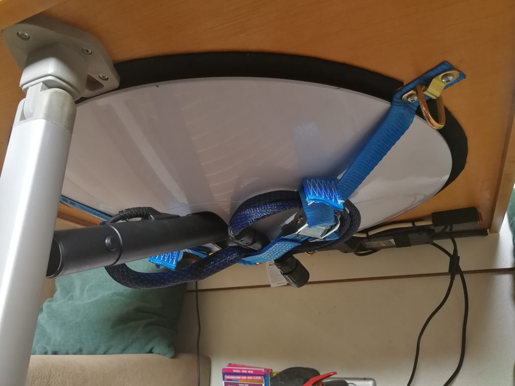
To store Dishy while not in use and while driving we now attach it to the underside of our table. This location is quick and easy to access and does not get in our way whilst sitting at the table. To protect Dishy’s face we have glued some felt fabric to the underside of the table. Dishy is then held in place with a three-legged strap system.
I have also cut down the dish cable by approximately 95’ (29m) as the full length is not required when Dishy is being used on the roof. As a bonus, the average power consumption appears to have reduced by approximately 5.5W to 94.5W. I added two clip-on ferrite cores to the shortened cable to effectively replace the one on the original cable section that has now been removed. I have also added a waterproof socket on the end of the long cut off cable so that it can be used as an extension cable should we want to use the tripod and mount Dishy away from the vehicle.
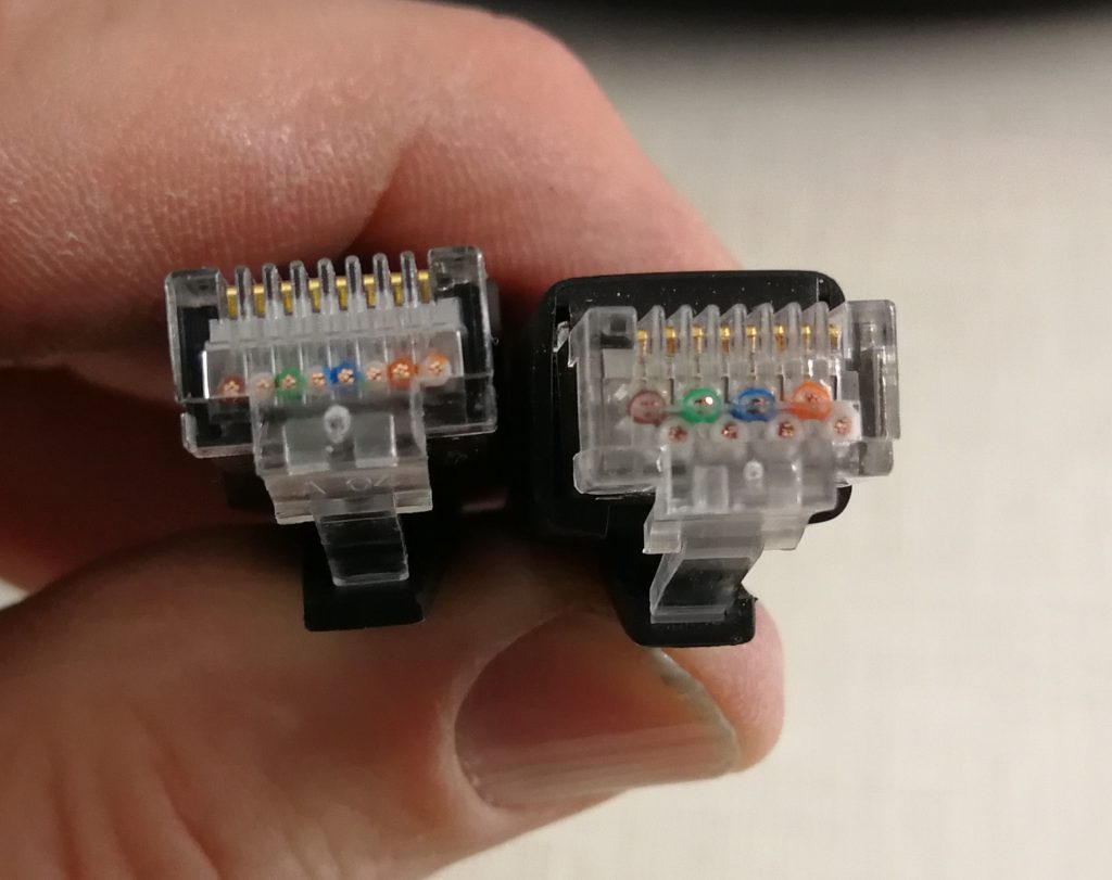
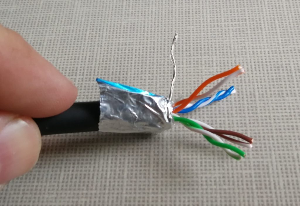
The dish cable colour coding appears to follow the RJ45 Ethernet cable T-568B straight through standard as follows:
- Pin 1 = white with orange stripe
- Pin 2 = orange
- Pin 3 = white with green stripe
- Pin 4 = blue
- Pin 5 = white with blue stripe
- Pin 6 = green
- Pin 7 = white with brown stripe
- Pin 8 = brown
Note: In the Starlink specifications (see here) they now list the ethernet cable pinout for the rectangular dish. It is the same colour coding as the round dish ethernet cable.
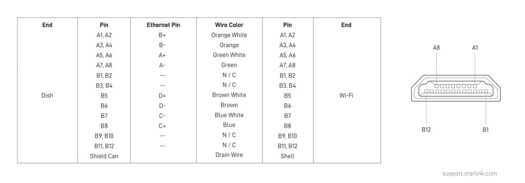
Cable screen to RJ45 screen (Screened RJ45 connectors should be used).
Update No. 2: 19 September 2021
SpaceX’s software updates have been improving the service, resulting in two significate effects on our installation:
1. The dish has become more sensitive to ‘slow ethernet connection’, so I have had to remove the ethernet junction I had made. It had originally worked well with early software versions, but now I simply switch the cable from the roof or lower socket to the power supply as required. This isn’t an issue for us as most of the time we use the roof cable.
2. There has been a significant reduction in power consumption with dish software “f9ff8ff1-b950-4524-8515-a105a2709cc4.uterm.release” that we received on the 26th of August 21. We are seeing a 20-watt reduction to an average power of 75 watts – this is a significant improvement for us.
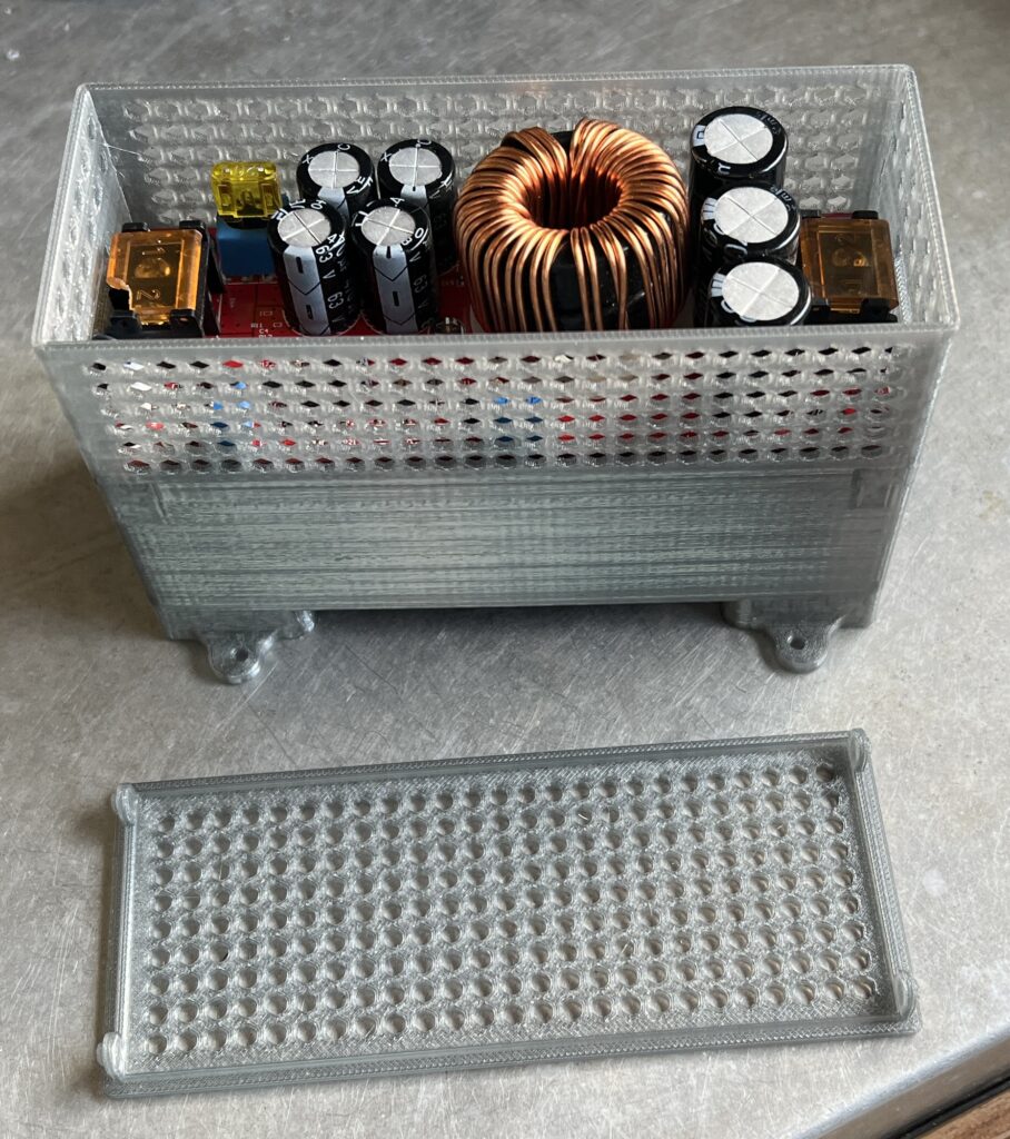
Update No. 3: Modifying the Starlink Power Supply to run on AC and DC
Living off-grid, or like us in a motorhome, power consumption can be critical. Having to convert our battery DC power into AC through an inverter, then back to DC through a power supply is not the most efficient way to power any device. We love having Starlink in our overlanding truck, but the power consumption can be a bit of a concern sometimes. So I wondered… would a DC power supply save a few valuable watts that are normally lost through the DC to AC to DC process? Click here for more information.
Update No. 4: Starlink Mobile Roaming
Now that roaming has been enabled on our Starlink, I have changed our installation to make the most of roaming. See: Starlink Mobile Roaming
Click here for our other Starlink pages.
Update No. 5: Rectangular Dish
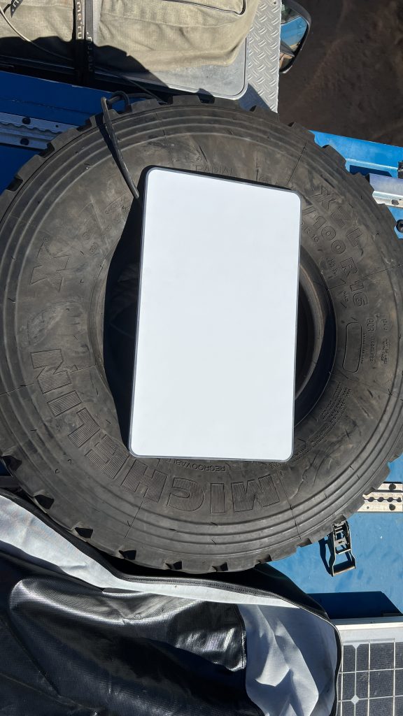
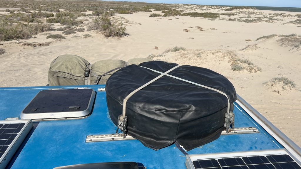
Unfortunately, we were not allowed to update our registered address to Mexico from the USA. We have therefore sold our round dish to an American family and purchased a new rectangular dish for Mexico. With the circular dish we have liked having it mounted flat on the roof of the truck (in the spare tyre, see more here) as it saves us having to set-up and take-down the dish when we want to drive. So this is how we installed the rectangular dish on Cuthbert.
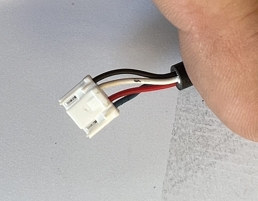
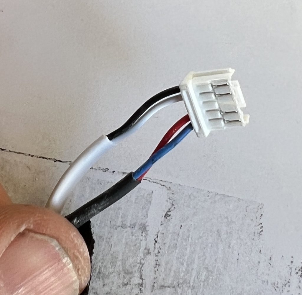
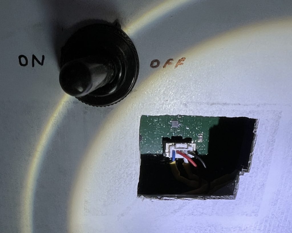
I cut a hole in the back of the dish so that I could install a switch to disable the motors. This will allow the dish to be flat mounted like we did with our round dish. I followed Pat Chicas’ directions for hole location (see more here). The two motors are wired into a single plug. The black and white wires go to one motor and the red and blue wires to the other motor. I cut the white and blue wires, extended them, and connected them to a double pole switch.
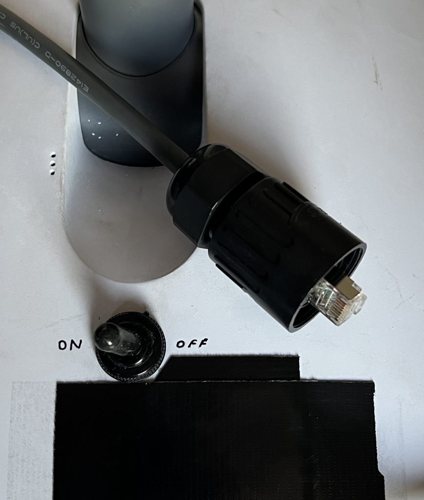
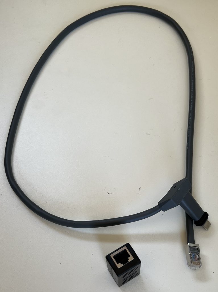
To make the installation as easy as possible, I am reusing the existing Starlink wiring in the truck. I cut the cable about a meter from the dish and installed a waterproof shielded RJ45 connector wired to T-568B standard (see round dish installation details above). This connector can be plugged into the existing Starlink cabling that I installed for our round dish. Note: Wiring to T-568B standard allowed me to power the Rectangular Dish using the power supply from my Round Dish!.
At the router end, I also cut the cable and installed a shielded RJ45 connector wired to T-568B standard. This is joined with the existing Starlink cable from our round dish installation, using a shielded ethernet joiner.
I also modified the router to run on DC, see here. While modifying the router for DC operation I also drilled three holes in its case so it could be screwed to the wall of the electrical cabinet.
Like the round dish was, the new dish is mounted inside our spare tyre on the roof. It’ obviously not quite such a perfect fit, but the tyre cover goes over the top of the dish to give it some protection from low tree branches and to make it less visible. The tyre cover has not had a significant effect on performance. The operating temperature under the cover has not triggered any thermal throttling issues either.
You may also be interested in my Starlink POE Injector design, see here.
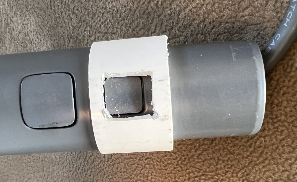
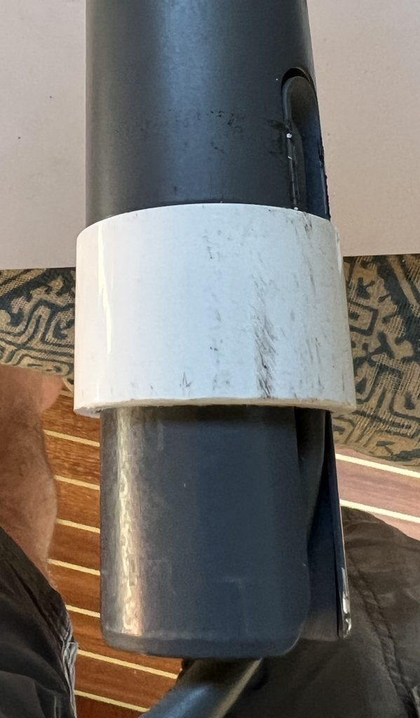
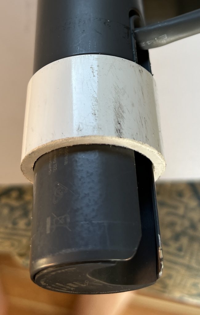
Update No. 6 – Cable Retention Collar
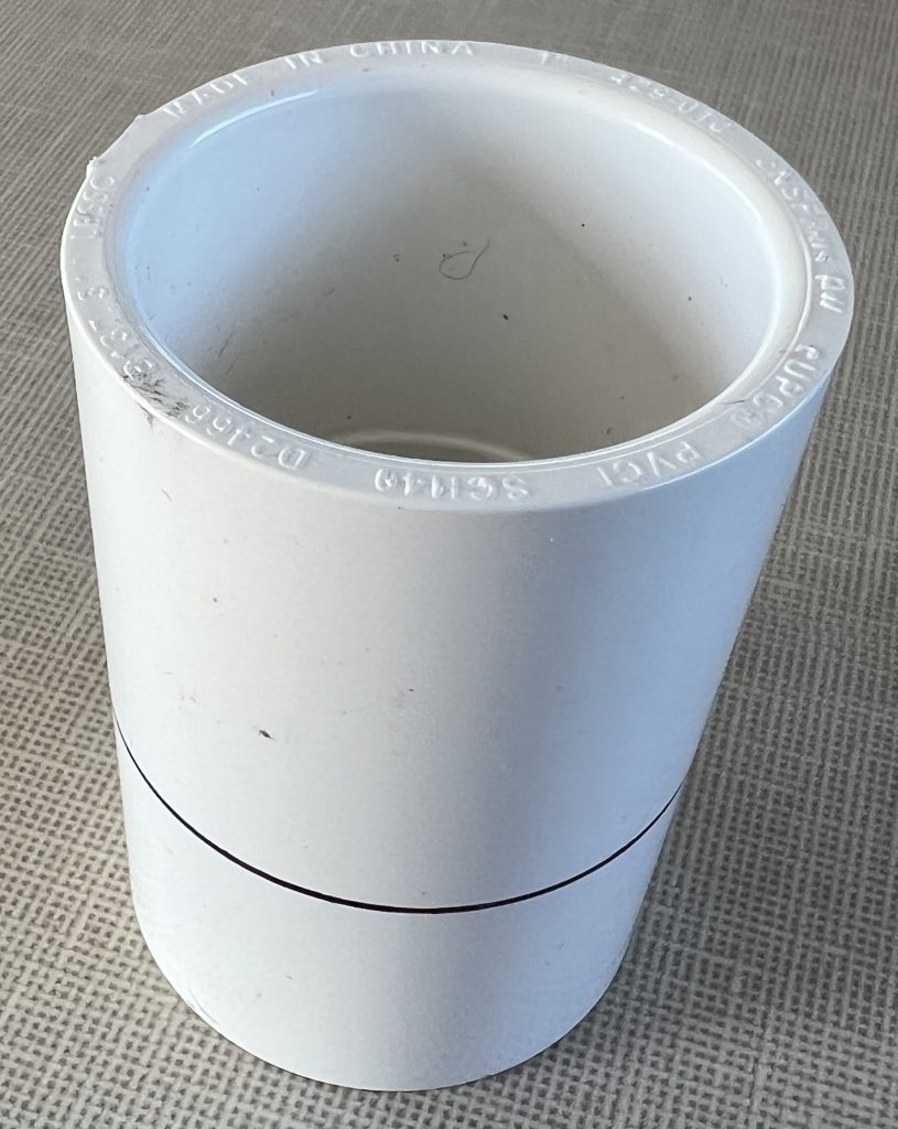
With the dish mounted flat and not using a stand or mounting, there is nothing to stop the plug in the bottom of the dish mast from coming loose. I have therefore made a small plastic collar that clips onto the end of the dish mast. This holds the plug firmly in place.
I used a plastic water pipe joint with an internal diameter close to the required 34 mm. It did take a little filing to make it a good sliding fit on the dish mast. I made a small cut out on one side for the latch on the dish mast to engage in. The plug is now held firmly in position and the cable can be routed out the side or bottom of the dish mast.
Update No.7 – Tp-link Archer AX50 (AX3000) Router Installation
The Starlink router is okay, but that’s about all that can be said about it. There are very few controls and options to set up the WiFi. We have also been a little disappointed with its range outside the truck. So I decided to try a 3rd party router and chose the Archer AX50 (AX3000).
Connecting the router
With the round dish there are two options:
a) simply connect a 3rd party router WAN port to the power supply white socket, and use it in place of the Starlink router; or
b) connect the 3rd party router WAN port to the AUX port of the Starlink router. The problem with this option is that you then have two routers running and 2 sets of WiFi. This is not ideal and is a waste of power, but it’s how we used to provide a guest Wifi using a small Alpha Campro R36 router.
With the newer rectangular dish, you need to buy an ethernet adapter. Then you can connect the 3rd party router WAN port, and put the Starlink router into by-pass mode (which effectively turns off the Starlink WiFi).
I have put together a ‘pick-and-mix’ system partly from my old round dish, and partly from my new rectangular dish. I used the round dish power supply which I had converted to run on DC. By installing a shielded RJ45 connector (wired to T-568B colour code, see here) on the cable coming from the rectangular dish, it can be plugged into the round dish power supply. I have seen that others have done this and operated the rectangular dish at the round dish voltage of 56V. However, as my system is adjustable, I have lowered the power supply’s voltage to 48V, which is the standard voltage of the rectangular dish.
WAN Internet Settings
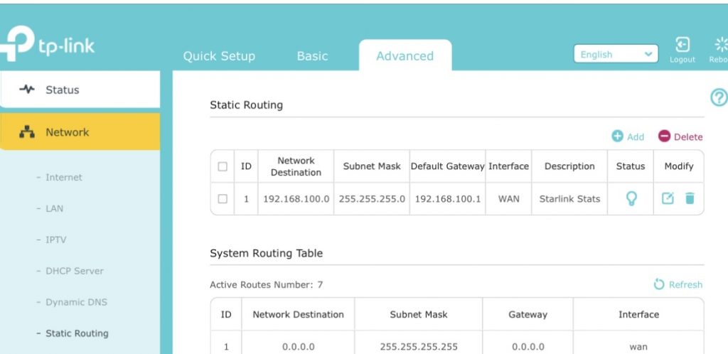
For a 3rd party router to work with Starlink, its WAN Internet settings need to be set to ‘Dynamic IP’. To use the Starlink app or a web browser to view the Starlink Statistics, you need to set a ‘static route’ in the 3rd party router. For our Archer AX50 router, this is done in the Advanced Network setting. These are the required settings:
Network destination: 192.168.100.0
Subnet Mask: 255.255.255.0
Gateway: 192.168.100.1
Interface: WAN
Snag solving
One issue I encountered with the Archer AX50 router was it frequently dropping the internet connection. A bit of searching on-line showed this to be a known issue that some routers have with Starlink – it’s to do with Starlink having short breaks in connection and losing DHCP addressing.
I found an article here: https://community.tp-link.com/en/home/forum/topic/563220
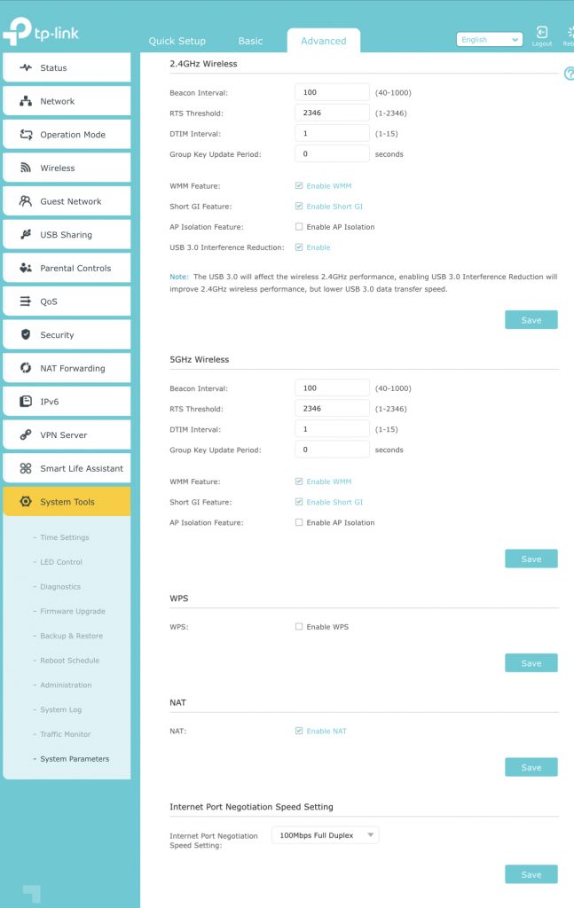
The article doesn’t specifically cover the Archer AX50 router, but I tried setting the ‘Internet Port Negotiation Speed Setting’ to ‘100 Mbps Full Duplex’. This didn’t fully solve the issue, so I found the solution was to install a small, cheap, switch between the Starlink and the router.
Advantages and Disadvantage of the 3rd Party Router
Now fully installed, the new Archer AX50 router advantages for us are:
- a true guest WiFi that can be switched on/off (so we can share our Starlink with other campers in remote locations);
- a USB port for connecting external hard drives for backing-up data accessible over the WiFi;
- a much greater range Wifi (we can now get WiFi over 450m/1476’ from Cuthbert – no more loss of signal if we want to sit outside away from the truck).
Archer AX50 router disadvantage for us is:
- higher power consumption, increase of 8W.
We can easily switch between the Archer AX50 and Starlink router. So, in areas where we could be critical on power, we can switch back to the Starlink router to save some power.
Sources
Website for the Archer AX50 router: https://www.tp-link.com/us/home-networking/wifi-router/archer-ax50/
The switch I used: https://amzn.eu/d/3ltkNKF
You may also be interested in my Starlink POE Injector design, see here.
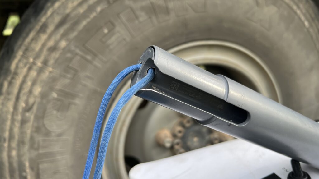
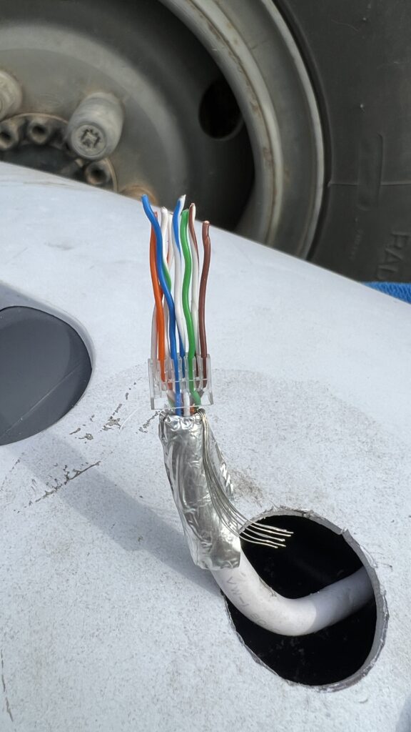
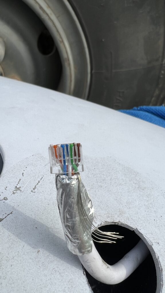
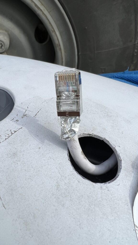
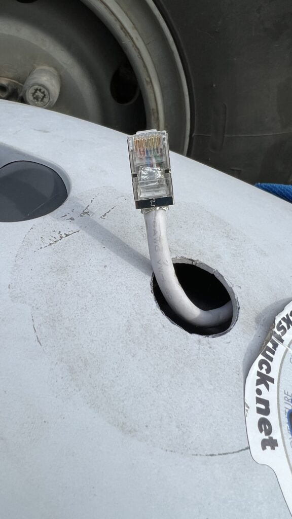
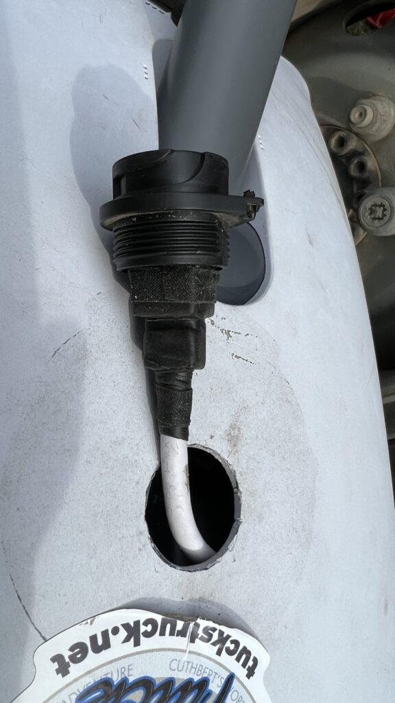
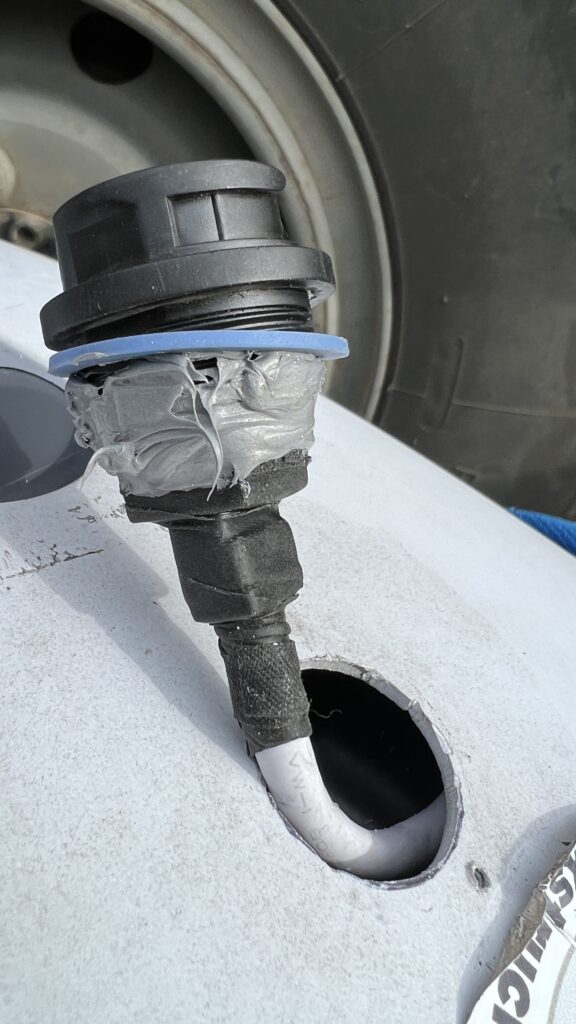
Update No. 8 – Dish RJ45 socket modification
The weak link with the rectangular dish is the connector in the mast of the dish. The connector easily becomes loose, even when installed in the stand, which eventually leads to the electrical failure of the connection. We had very strange behaviour from the router: it was disconnecting devices from the WiFi and we were unable to connect again. At first I thought this was a router failure and so connected the dish to a 3rd party router via a POE injector. Using the 3rd party router, I discovered that the dish was intermittently disconnecting. I checked the dish connector and it was not firmly into position. After firmly reconnecting the dish cable, I reconnected the Starlink router and it functioned correctly again. Quite why a disconnecting dish would effect the router in this way is bit of a mystery, I would have expected it to just show the dish as disconnected.
This for me was the last straw! I decided it was time to delete the Starlink proprietary plug and socket. So I checked what Oleg had to say…
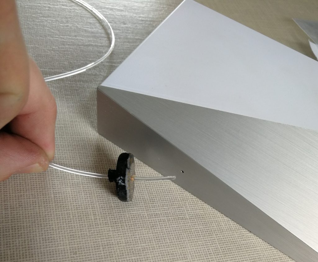
Oleg has been repairing battle-damaged Starlink terminals in Ukraine and has a lot of experience modifying them too. He has done a great video showing how to install a waterproof RJ45 on the back of the dish. See: https://youtu.be/GKYMd9tDlew
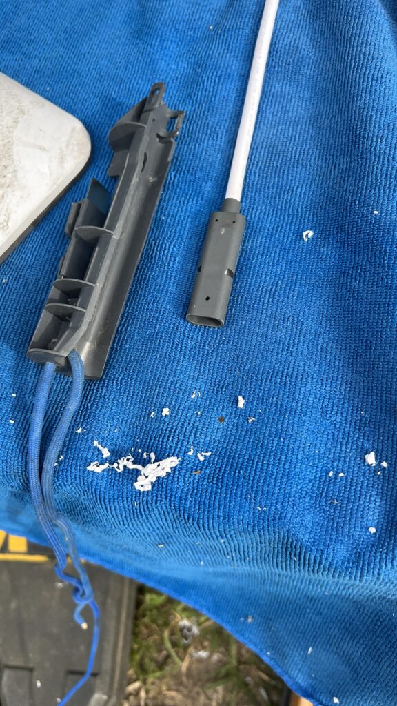
The only change I made to his technique was to drill a hole in the mast insert, so that I could attach a cord.
This allowed me to push the insert further into the mast, so I had a longer length of cable to work with, then pull it out again using the cord. After cutting the cable, I fully removed the insert and then removed the socket from it before reinserting the insert.
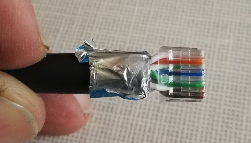
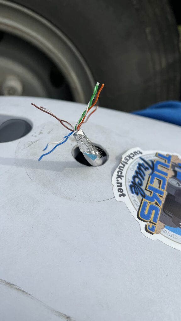
The shielded RJ45 plug is wired to T-568B colour code (as are all my Starlink cables).
- Pin 1 = white with orange stripe
- Pin 2 = orange
- Pin 3 = white with green stripe
- Pin 4 = blue
- Pin 5 = white with blue stripe
- Pin 6 = green
- Pin 7 = white with brown stripe
- Pin 8 = brown
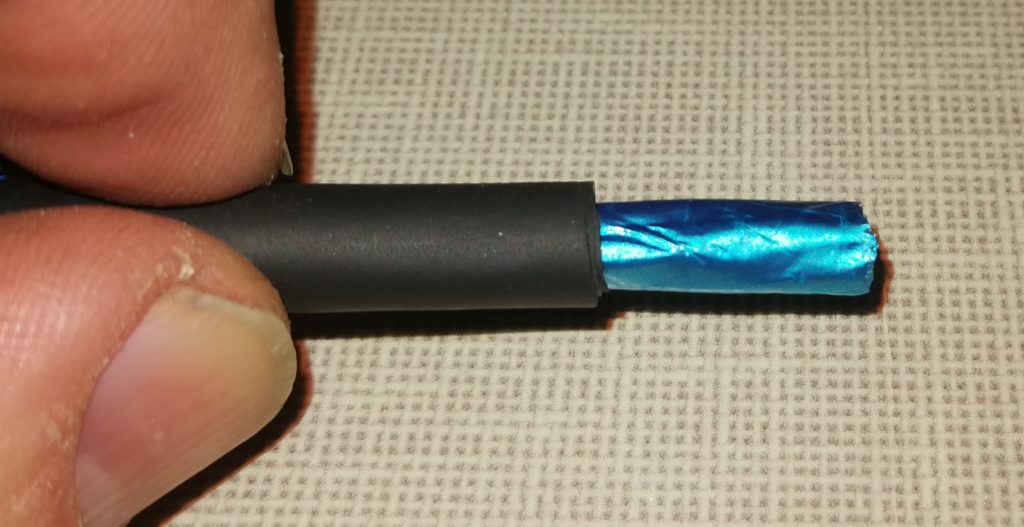
The pictures below show some more detail:-
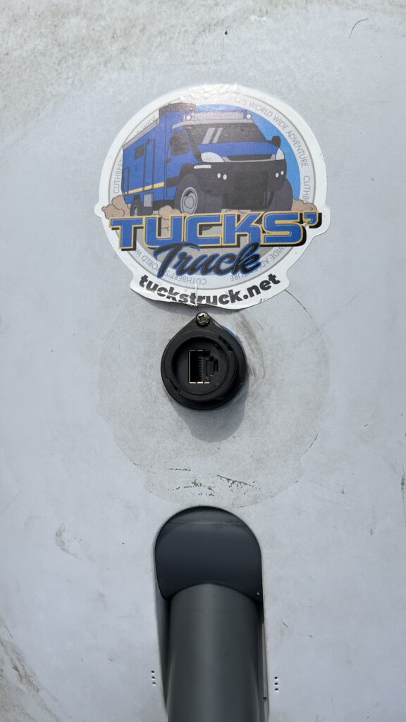
Update No. 9 – Gen 3 Starlink Installation
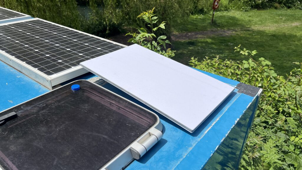
We have now upgraded to the Gen 3 Starlink. I used the Starlink Mobility Mount Kit for securing the dish to the truck roof. Although the kit comes with some large screws and bolts, our roof structure is not suitable for them to ‘grip’ into. Our roof is constructed from a sandwich panel consisting of a 2 mm outer plastic layer, 50 mm of insulation and then another skin of 2 mm plastic on the vehicle’s inside. This is an incredibly strong, well insulated and light construction material used by many of the top expedition vehicle manufactures in Germany. It has certainly stood up to the rigors of our overlanding over the last 10 years or so. But I believe that, unless it was bolted all the way through the roof, the screws/bolts would not provide enough retention for the bracket. This would lead to a possibility of leaks and form a thermal bridge, neither of which is acceptable to us. I have therefore bonded the bracket to the roof using Silkaflex 554, https://amzn.eu/d/07dZyAmo with the supplied screws effectively just holding the bracket in place while the glue dries (the screws only go through the outer roof skin).
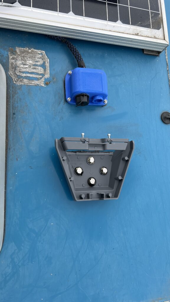
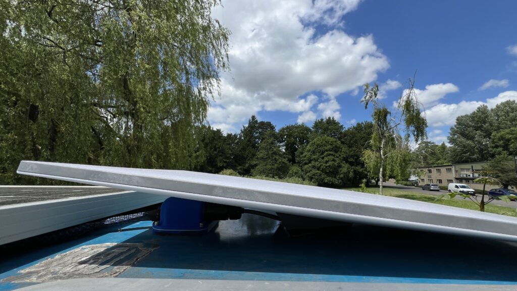
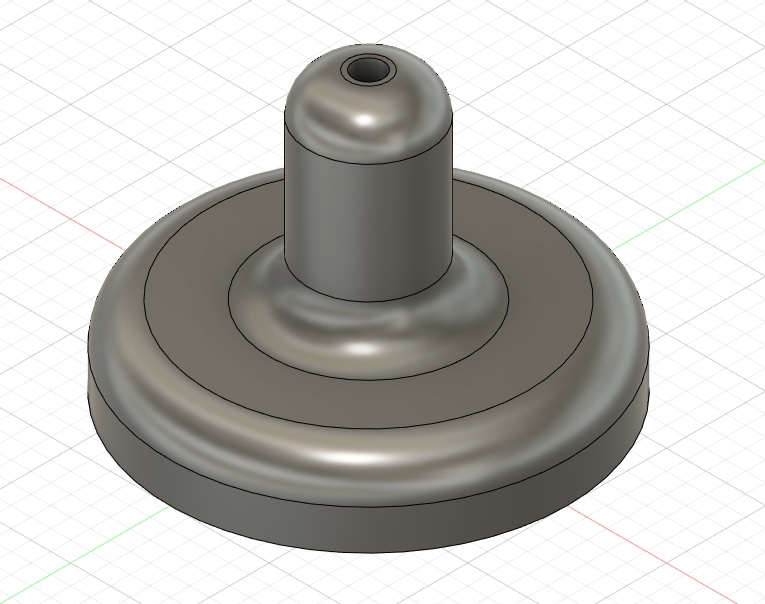
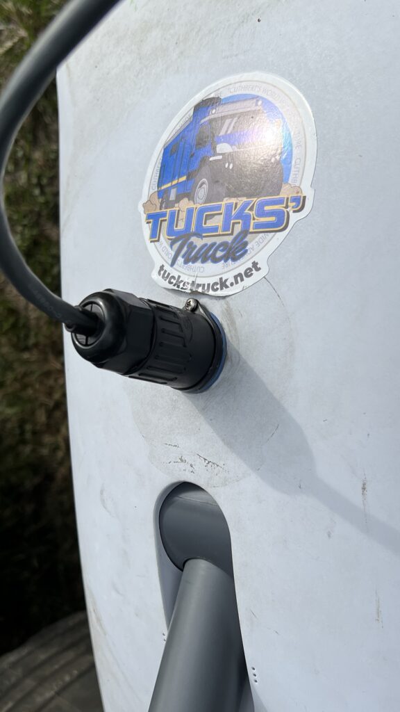
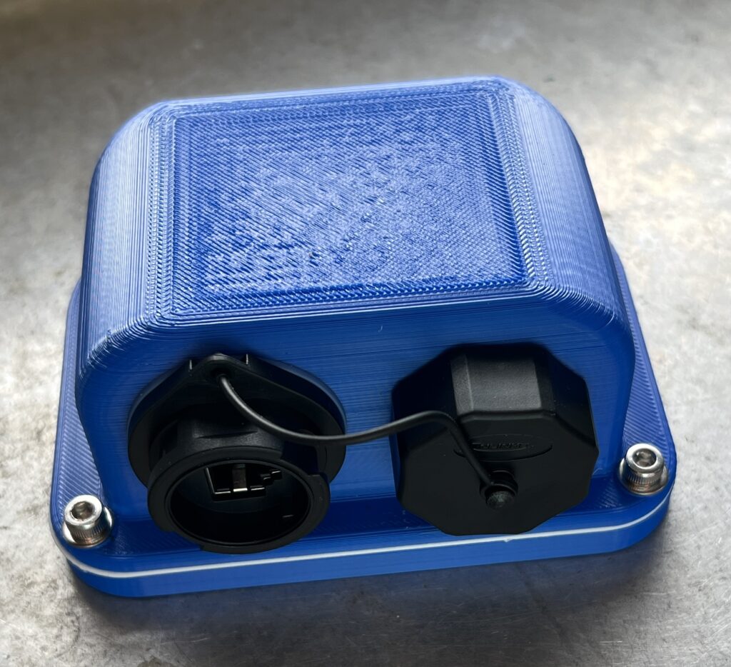
For the electrical connection I reused the existing Starlink cable on the roof, but have designed and printed a new electrical box. This box holds a waterproof RJ45 connector and has a storage fitting for the connector’s cap while the socket is in use. The file for this box can be downloaded and printed from here: https://makerworld.com/en/models/460717#profileId-369274 The connectors I use are these: https://a.co/d/4mNPBWL
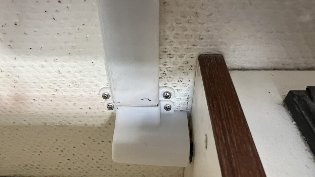
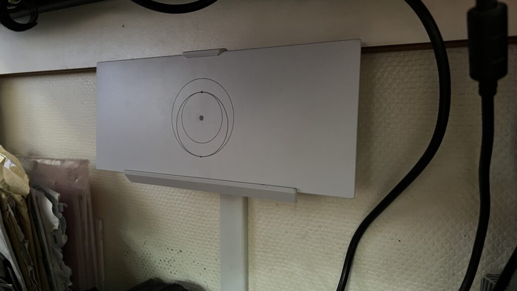
Inside the truck I have mounted the Gen 3 router below the table using the Gen 3 Starlink Router Mounting kit. I routed the cabling behind a 3D printed conduit to keep it neat and tidy.
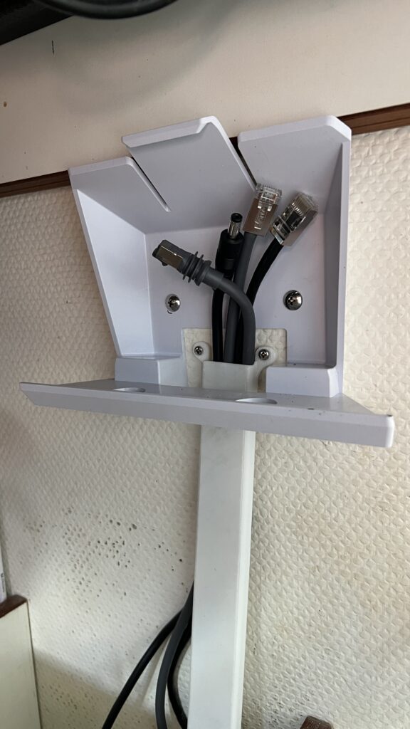
To power this dish I have once again used my DC to DC power supply, see update 4 for full details: https://tuckstruck.net/truck-and-kit/geekery/modifying-the-starlink-power-supply-to-run-on-ac-and-dc/#update4
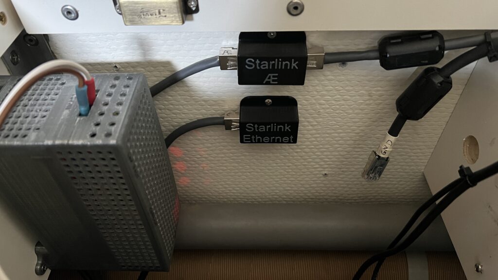
I have used a shielded ethernet connector so that I can switching the router to dish connection between a connector on the roof and one mounted in a lower equipment locker. This equipment locker socket is useful when I want to use the dish away from the vehicle on an extension cable (e.g. if we are parked under a tree etc.). The other coupler is a convenient place to attach other equipment to one of the router’s spare ethernet sockets. The ethernet couplers I have used are: https://www.amazon.ca/dp/B07C3R34BX?ref=ppx_pop_mob_ap_share
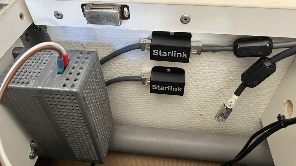
I have 3D printed covers for these ethernet couplers so they could be screwed to the wall see: https://makerworld.com/en/models/492783#profileId-406408 then I changed the labelling to make them more appropriate: https://makerworld.com/en/models/492789#profileId-406413
1 Marcus has a Master’s degree in Avionic Systems and over 25 years operational experience in military avionics
2 The ‘Regulatory Notices’ is the piece of (ridiculously tiny-print) paper that comes in the box with warnings and tech-info in around 500 languages. Most people ignore it, put it to one side and use it for fire-kindling at their next overlanding camp-spot.